Code 52 Code 53 Code 92
TAKE-OFF, SPD, DIST Flap Trim Arrangement Switch Slow-Down
Pre-sets for the Flight Tasks Signal Generator Selection for the Flap Function Elevator / Flap Transit Time Slow-Down
39
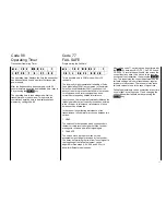
S T A R T F L A P + 5 8
E L E V + 7
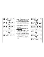
Code 52 permits storing the flap and elevator settings
for Speed, Distance and for the Take-Off phases.
However, the allocation of the corresponding external
switches has to be performed first using code 23.
A possibly active aileron
rudder mixer (code 41)
will automatically be switched off when the Speed
flight task is selected on.
For these adjustments the corresponding external
switch has to be actuated after calling code 52,
whereupon the values for elevator and flaps will be
displayed. Adjustments are made using the
INC
and
DEC
keys, by pressing the
TURN
key the elevator
and flap adjustments can be changed and the value
set directly to 0 by the
CLEAR
key.
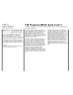
N O R M A L I N P 6 = O N
I N P 7 = O F F
The operating elements for actuating the flaps can be
selected separately from the pre-set flight tasks
duration (normal), distance, speed and the start
phase. Operating elements can be slider-type, rotary
potentiometers or step switches, which are wired to
the plug stations for channel 6 and 7. Between the
two inlets a fundamental difference exists.
While the signal generator wired to channel input 6
also affects mixer code 48 (flap
elevator), inlet 7
may be used for elevator independent flap trim. For
any of these four phases of flight you can select
whether the flaps function is to be performed by the
signal generator of channel 6 or 7, or by neither of
these. For example, you may actuate the flaps for the
duration phase by slider-type control 6, for distance
flight by a switch module providing three switch
positions, and for the start and speed phases
exclusively by the pre-set values without any further
adjustment being possible.
Adjustment
After calling code 53, a selection menu appears on
the display for the active flight phase concerned,
selected by actuating the external switch in question.
Using the
INC
and
DEC
keys you can switch the
values between ON and OFF, or the
CLEAR
key for
OFF. Using the
TURN
key permits swapping
between adjustment of channel 6 or 7. For selection
of another flight phase the corresponding switch has
to be actuated, whereupon the display will change
accordingly.
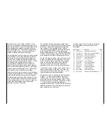
S m o o t h E L E = O F F
F L A = 3 . 3 s
In order to avoid abrupt elevator and flap deflection
when switching between the pre-sets for the various
flight phases, the transit time of the servos for
elevator and flap can be adjusted separately, by
code 92, within the range 0.5s to 30s for full servo
throw. In the case of the elevator this slowing down is
effective only when switching from one flight phase to
another one, not in the course of normal control. In
the case of flaps it is permanently effective, so the
flaps can be operated smoothly with a 3 position
switch without jerking.
After calling code 92, the transit time can be adjusted
by the
INC
and
DEC
keys. For smaller delay values
the steps are very small and not every change will
show on the display. Steps increase in size as the
delay value increases. By pressing the
CLEAR
key
the slow-down is cancelled, while pressing the
TURN
key swaps between adjusting the elevator and
flaps setting.
Summary of Contents for mc-18
Page 1: ...1...
Page 10: ...Block Diagram NORMAL 10...
Page 11: ...Block Diagram NORMAL DIFF 11...
Page 12: ...Block Diagram DELTA DIFF 12...
Page 13: ...Block Diagram UNIFLY DIFF 13...
Page 14: ...Block Diagram Quadro Flap 14...
Page 15: ...Block Diagram F3B 3 wing servos 15...


