Programming Examples
for Fixed-Wing Models
52
12.) Throw Reduction
Unlike throw adjust, servo reaction to a control stick
deflection remains unchanged, provided the pre-set
threshold value is not exceeded. On reaching the
threshold value, the servo will simply stop there, eve
when the stick concerned (or some other signal
generator) is moved beyond that point. It does not
matter by which of the means the servo reaches the
threshold value(by control stick alone or by the
interaction of mixers). The only importance is that the
threshold can not be exceeded by the servo. In our
example we wish to adjust the threshold for the
elevator in such a way that jamming of the rudder can
not occur, while the elevator action remains normal
and no concern is needed over the upward deflection
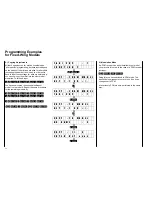
of the control surface. Throw reduction is access by
code 19:
1
9
ENTER
Select the elevator channel by entering number and
hold the elevator in the “full up” position. By pressing
the
DEC
key you may now reduce the threshold
(normally at 150% of normal servo throw) to a value
which prevents the elevator hitting the rudder.
When pulling the elevator stick slowly you’ll notice
that the servo follows the stick in a normal manner,
until it stops a the threshold value, resulting in a
“dead” range having been created at the end of the
stick travel. It will become larger, if up trim has been
added.
This example permits recognising the action of throw
reduction, although its normal field of application is in
the interaction of several mixers on a specific servo,
used for example in the case of plain flaps and
flaperons of large sailplane models. Here the
threshold action can be set just short of a point where
otherwise linkages or hinges would flex or deform.
T A X I C U P : 1
F U N C T I O N ?
1
9
ENTER
↓↓
T H R O W L I M I T
p u s h c h k e y 1 - 9
3
↓↓
T H R O W L I M I T
3 c h - E N D 1 5 0 %
DEC
↓↓
T H R O W A D J U S T
3 c h - E N D 9 4 %
ENTER
↓↓
T A X I C U P : 1
F U N C T I O N ?
13.) Adapting Throttle Characteristics
If you have flown your power model in the meantime,
you may have noticed that while engine speed can be
adjusted between idle and full throttle via the throttle
stick, the RPM adjustments are not uniformly
distributed along the stick throw. In most cases
engine speed adjustments for idle to 80% of full
throttle will occupy the lower half of the control stick
movement, while the upper half of the stick travel has
little effect. This depends on the carburettor used of
course, but it is typical nevertheless for nearly all
engines. The desirable carburettor characteristics
would be for the RPM to follow the stick travel in a
linear manner.
The PROFI-ULTRASOFT-Module also provides an
adjustment option to allow compensation of the above
mentioned non-linearity – neutral point offset can be
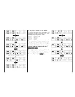
called up for channel 1:
3
1
ENTER
The indicated value 0% mean linear operation of the
carburettor control lever by the servo. In the case
described above the actuation has to be a
progressive one compared to the regressive
behaviour of the carburettor. The servo position for
the stick neutral point needs to be offset in the
direction towards idle, which can be accomplished by
press the
INC
key. Adjustments should preferably be
made with the engine running until a continuous rate
of engine RPM change has been achieved. Terminate
adjustments using the
ENTER
key.
Summary of Contents for mc-18
Page 1: ...1...
Page 10: ...Block Diagram NORMAL 10...
Page 11: ...Block Diagram NORMAL DIFF 11...
Page 12: ...Block Diagram DELTA DIFF 12...
Page 13: ...Block Diagram UNIFLY DIFF 13...
Page 14: ...Block Diagram Quadro Flap 14...
Page 15: ...Block Diagram F3B 3 wing servos 15...


