Programming Code List (Types 1…5)
17
The codes for the various options were chosen
as a result of in-house deliberations. The
following programming instructions, are arranged
in the sequential order of the individual
programming steps. These are ar ranged to suit
practical requirements, the code numbers are
not arranged in numerical order.
When a new model is being programmed, be
sure to follow the sequences detailed in the
following pages. If you don’t follow it, you may
forget something or uninten tionally change other,
earlier made adjustments.
In subsequent descriptions functionally related
options have been grouped together, so they will
be comparatively easy to fund.
No. Display Meaning Page
Transmitter Basic Adjustments
56 MODEL SELECT Select Model 18
95 MODULATION PPM/PCM Select 18
57 MODE SELECT Stick Mode Selection 18
58 MODEL TYPE Model Type Selection 19
32 MODEL NAME Input Model Name 19
18 IDLE R. TRIM Idle Trim Adjustment 19
23 SWITCH FUNCT. External Switch Allocation 20
37 INP-PORT ASS Allocation of External Controls 21
Model Basic Adjustments
43 V-TAIL SW V-Tail Mixer 21
11 REVERSE SW Direction of Rotation of Servos 21
15 SUB TRIM Servo Neutral Point Adjust 22
12 THROW ADJUST Servo Throw Adjustments 22
19 THROW LIMIT Servo Throw Reduction 22
79 SERVO SLOW-D Servo Slow Set-up 23
Further Adjustments
16 TRACE RATE Adjust Effect of Operating Stick 23
31 THR/BRK MIDP Set Channel 1 Mid-Point 23
34 SWITCH DR/EXP Dual Rate/Exponential Switch Set-up 24
13 DUAL RATE Switchable Servo Throw Reduction 24
14 EXPONENTIAL Exponential Servo Movement 24
35 RED. TRIM Allows Reduction of Trim Range 25
Special Functions
59 TRIM OFFSET Storage of Trim Offset Values 25
94 COPY MODEL Model Copy Facility 26
22 DIFF. RATE Aileron Differential 27
17 RED. THROTTLE Switchable Throttle Reduction 28
66 PROGRAM-AUTOM Automatic Manoeuvre Set-up 28
63 CH1-SWITCH Channel 1 Dependant Auto Switch
29
Freely Programmable Mixers
51 MIXx CHANNEL Channel Allocation for Mixers 30
33 SWITCH MIX Allocation of Mix Switches 31
61 MIXx COM GAIN Mixer No x Common Gain Adjust 31
71 MIXx SEP GAIN Mixer No x Separate Gain Adjust 31
72 MIX ONLY CH Allows Isolation of Control from O/P
32
No. Display Meaning Page
Clocks:
97 ALARM TIMER Stop Watch Timer 32
98 INTEG. TIME TX operating Timer 33
Safety Devices
77 FAIL SAFE MEM Set-up of Failsafe Mode 33
78 FAIL SAFE BAT Failsafe on Low RX Battery 34
88 KEYBOARD LOCK Lock the Keyboard 34
99 ALL CLOSE Lock the Transmitter 34
Test Functions
76 SERVO TEST Allows Testing of Servos 35
74 SERVO POSIT. Display of a Servo Position 35
73 SWITCH POSIT. Display of Switch Positions 36
Summary of Contents for mc-18
Page 1: ...1...
Page 10: ...Block Diagram NORMAL 10...
Page 11: ...Block Diagram NORMAL DIFF 11...
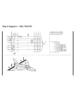
Page 12: ...Block Diagram DELTA DIFF 12...
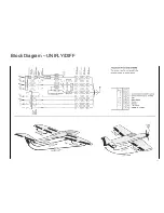
Page 13: ...Block Diagram UNIFLY DIFF 13...
Page 14: ...Block Diagram Quadro Flap 14...
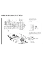
Page 15: ...Block Diagram F3B 3 wing servos 15...


