Code 63
Channel 1 Switch
Automatic Channel 1 Dependent Switch (Throttle/Spoiler)
29
C H 1 - S W I T C H = ?
For special functions it is desirable not to perform
switching by an external switch, but automatically via
the channel 1 stick (throttle and spoiler), whereby
exceeding a critical stick position provides switch
position ON, while falling below provides switch
position 0, or vice versa.
The threshold point can be placed anywhere along
the stick travel and the modeller can decide whether
the upper or lower portion is to activate switch
position to the ON state. The automatic switch is
allocated to one of the external switch connectors
(1…8) whereby it is unrestrictedly included into the
free programmability of the external switches via
codes 23, 33 and 34.
If a normal switch is also wired to this connection, the
two switches (e.g. the external switch and the
automatic one) will be wired in parallel. With reversal
of polarity being possible with either type of switch,
logical links between the two of them can be realised.
“AND“ Link
Both switches must be closed so the connected
function(s) can be performed.
“OR” Link
The connected function(s) is (are) performed when
either switch is closed.
As a result the external switch may be used to
perform automatic switch over by the stick. By
including the automatic switch into a free allocation of
external switch any combination of functions can be
switched in dependency of the control stick position.
So, by turning on the correspondingly programmed
misers, flaps can be lowered when throttling the
engine and the elevator re-trimmed (Auto-Landing), or
dual-rates may be switched to increase control
surface throw in the landing approach at reduced
speed. Pilots of electric flight models can turn the
timer on and off via the automatic switch for checking
motor run synchronously with the main drive motor.
Programming:
After calling, via code 63, the transmitter, as in the
above display, indicates it is waiting for the input of
the external switch connection (1…8), to which the
automatic switch is to be allocated. After the
connection number (e.g. “6”) has been input the
display will read like:
C H 1 - S W I T C H = 6
=
C H 1 S =
P 6 =
Here the interaction of the automatic switch and a
possibly connected external switch is shown. The
stylised control stick at the left of the lower line
indicates the direction of deflection of the
throttle/spoiler stick with the switch in the open
position. Direction can be reversed by hitting the
TURN
key.
The switch state (open or closed) of the channel 1
switch is indicated in the centre of the lower line. By
moving the stick the function can be checked and the
threshold point be adjusted. To do this the stick is
moved to the position at which switching is to occur,
then press the
STORE
key.
The right end of the lower line displays the switch
state of a switch wired to its allocated external switch
connection.
The interaction of the external switch and automatic
channel 1 switch is displayed at the right end of the
upper line of the display.
The allocation of the channel 1 switch is cancelled by
pressing the
CLEAR
key.
Summary of Contents for mc-18
Page 1: ...1...
Page 10: ...Block Diagram NORMAL 10...
Page 11: ...Block Diagram NORMAL DIFF 11...
Page 12: ...Block Diagram DELTA DIFF 12...
Page 13: ...Block Diagram UNIFLY DIFF 13...
Page 14: ...Block Diagram Quadro Flap 14...
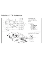
Page 15: ...Block Diagram F3B 3 wing servos 15...


