Programming Examples for Fixed-Wing Models
44
In case you have become slightly confused by the
unusually large number of functions offered in the
preceding chapters of these instructions, the following
pages show you by way of example, how a practical
adjustment of a model can be programmed in a
minimum of time. In doing so, the essential functions
will be activated, while the “deluxe” options meant for
the competition pilot will not, initially, be taken into
consideration. In the following chapters this basic
program will the be expanded by additional options,
followed by a few examples for the Profi’s bag of
tricks. Here the basic principles of computer R/C will
become clear.
From the extensive range of functions you select only
those which are actually required and forget the rest
of them. If, in the course of time, you need more all
you have to do is activate additional functions.
Be sure to duplicate the following examples step by
step, so you won’t forget or overlook anything. In this
manner you’ll actually get automatically familiar with
your R/C equipment and won’t consider it nearly as
complicated as it may have appeared at first glance.
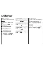
1.) Preparations
You have installed the module into the transmitter as
per the instructions. Close the case of the transmitter
again and turned the transmitter on. The display will
read:
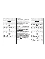
m c - 1 8 E M O D E L 1
9 . 6 V P C M
Depending on what kind of module had been installed
previously in your transmitter the display may show
another model number or another modulation mode.
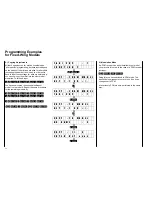
2.) Executing RESET (Important)
Call model memory 1 and clear it completely. To do
this input:
ENTER
5
6
ENTER
1
CLEAR
ENTER
If the transmitter had previously been switched to
PCM you now have the basic position of the display
again. If not, the request will appear to turn the
transmitter off. This is because it has been switched
to the default position of PCM modulation. Comply
with the request and then turn it on again a moment
later, thereafter you will be in the basic position.
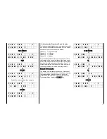
For safety’s sake, so you won’t forget it later, execute
a reset (right now) on all the remainder of the model
memories. To do this, input:
ENTER
5
6
ENTER
2
CLEAR
ENTER
ENTER
5
6
ENTER
3
CLEAR
ENTER
…
ENTER
5
6
ENTER
7
CLEAR
ENTER
…
(
ENTER
5
6
ENTER
3
0
CLEAR
ENTER
)
This procedure needs only to be performed once in
order to positively delete any programming parts and
data which may have been stored in the transmitter
memory by an earlier used module, and could still be
stored. These program fragments may cause a
malfunction if not deleted.
Summary of Contents for mc-18
Page 1: ...1...
Page 10: ...Block Diagram NORMAL 10...
Page 11: ...Block Diagram NORMAL DIFF 11...
Page 12: ...Block Diagram DELTA DIFF 12...
Page 13: ...Block Diagram UNIFLY DIFF 13...
Page 14: ...Block Diagram Quadro Flap 14...
Page 15: ...Block Diagram F3B 3 wing servos 15...


