Code 73
Switch Position
Display of Switch Positions
36
F3B Programs (Model Types 6 and 7)
Universal Profi-Programs for competition flyers, and also for other models such as large sailplanes featuring at
least 2 wing-mounted servos
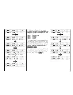
S w i t c h 1 2 3 4 5 6 7 8 9
For checking the installation of switches and their
connections to plug stations 1…8, the switch
positions of all external switched are indicated by
code 73, with an automatic channel 1 switch, possibly
programmed by code 63, being taken into account.
The display always refers to the actual mechanical
switch position of the switch concerned, independent
of its having possible been reversed by code 23, 33,
or 34.
Please Note:
In the case of mixers a closed switch will normally
turn off the mixer concerned, not on!
The F3B model programs (code 58, types 6 and 7)
have been developed for F3B class contest models in
close cooperation with renowned experts. The
competition program requires a model with three
different flight tasks, with only its ready to fly weight,
being permitted to be changed by adding or removing
ballast weights. Any other adjustments can only be
performed by remote control.
To be able to comply with these requirements, the
models of this contest normally feature plain flaps so
they can be adapted to the flight tasks of duration,
distance and speed, as well as the launch phase. In
addition they also servo as a landing aid. As a rule,
the flaps are lowered for take-off to generate as much
lift as possible, with the resulting drag being of little
importance as it is overcome by the towline winch
anyway. For hi-speed flight a slightly negative
deflection (meaning an upward one) may be
advantageous depending on the airfoil section, while
for distance flying the optimum angle of glide should
be found somewhere about the neutral setting of the
flaps.
For duration flying the lowest sinking rate will be
achieved by setting the flaps to a slightly positive
angle. That setting may have to reduced a bit for tight
circling flight in thermals and increased when
searching for thermals by flying wide circles to ensure
the optimum glide. On landing, the flaps are fully
deflected (positive) causing the airflow on the upper
surface to separate and increase drag, without
affecting the lift. This effect can be supplemented by
spoilers, if installed (in some cases spoilers are
dispensed with). Drag can be increased still more by
deflecting both ailerons upward in addition to the
extreme downward deflection of the flaps, this
combination results in a most effective control of glide
angle.
Summary of Contents for mc-18
Page 1: ...1...
Page 10: ...Block Diagram NORMAL 10...
Page 11: ...Block Diagram NORMAL DIFF 11...
Page 12: ...Block Diagram DELTA DIFF 12...
Page 13: ...Block Diagram UNIFLY DIFF 13...
Page 14: ...Block Diagram Quadro Flap 14...
Page 15: ...Block Diagram F3B 3 wing servos 15...

