Fixed-Wing Aircraft Programming
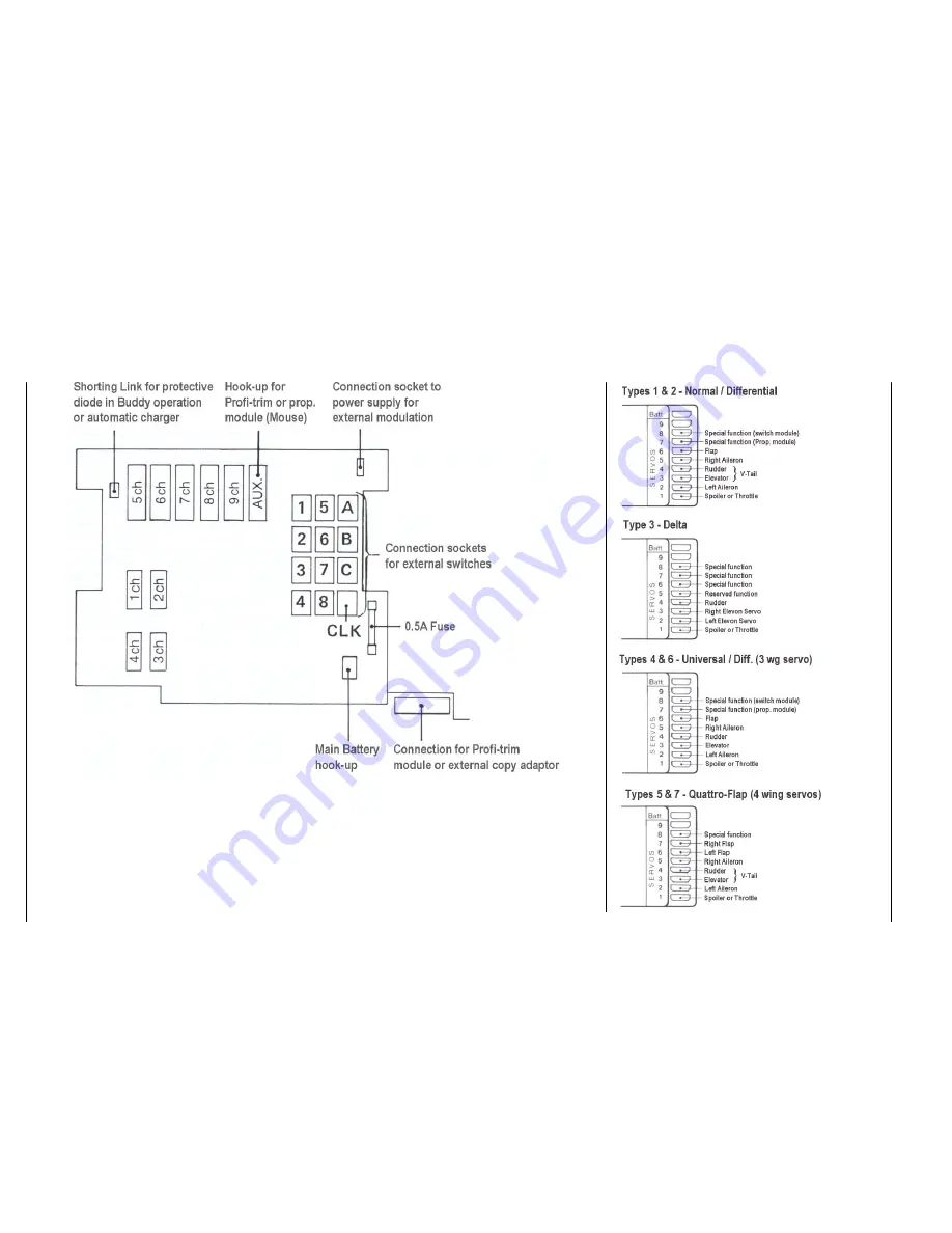
Hook-up of External Operating Elements at the Transmitter Board Allocation of Receiver Outputs
8
The operating elements wired to connections
5ch…9ch can be allocated differently, if so
desired using code 37.
If a three position switch (diff. Switch, order no
4160/22) is connected, for example to switch
aileron differential (code 22), the two plugs must
be plugged into horizontally adjacent stations
only (e.g. 4 and 8), never one above the other
(e.g. 3 and 4).
The external plug stations 1…8 are allocated to
the desired functions using codes 23, 33 and 34.
A switch (e.g. 4160/11) connec ted to the CLK
connection is used to start/stop the countdown
timer.
The connections A…C may only be used for the
automatic aerobatic manoeuvre (code 66).
Summary of Contents for mc-18
Page 1: ...1...
Page 10: ...Block Diagram NORMAL 10...
Page 11: ...Block Diagram NORMAL DIFF 11...
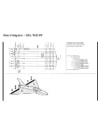
Page 12: ...Block Diagram DELTA DIFF 12...
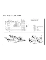
Page 13: ...Block Diagram UNIFLY DIFF 13...
Page 14: ...Block Diagram Quadro Flap 14...
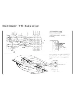
Page 15: ...Block Diagram F3B 3 wing servos 15...


