Code 23
Switch Function
Allocation of External Switches to Model Types 1 – 5
20
C L K D I 1 D I 2 P R G
N 9 9 N
External switches installed and connected to plug
stations 1 – 8 are allocated to specific functions via
code 23. Some of these functions can be activated
and de-activated in the process. Allocation can be
performed either as per the mechanical mode of
operation of the switch (open = OFF, closed = ON) or
by pole reversal (open = ON, closed = OFF).
In addition to physically existing switches a logical
“phantom switch” is available, designated numeral 9.
By allocation of this switch one of the functions can
be permanently switched on or off, respectively.
Allocation and pole reversal of external switches
After calling code 23, the functions available for the
active model will appear on the upper line of the
display, with the allocated switches appearing on the
line below. Numerals indicate the switches wired to
the corresponding plug stations.
N means that the function in question is de-activated.
Flashing numerals indicate that the switch concerned
has been allocated with reverse polarity. The small
arrow (upper line) indicates the function to which the
switch can be allocated at the present time. It can be
moved to the right or left by pressing the
INC
and
DEC
key, respectively.
As not all of the available functions can be shown at
the same time on the display, the latter can be moved
– window style – over the two lines, showing the
allocations. When the arrow points to the outermost
right function, the next function will appear in the
display when the
INC
key is pressed. They can be
scrolled left by pressing the
DEC
key. In this
manner any of the functions can be displayed.
To allocate the selected functions press the
CLEAR
key. As a result a question mark symbol will appear
on the lower line. To switch be may allocated by
pressing keys
1
…
9
. If the switch is to be reversed,
the
DEC
key has to pressed first.
If a de-activatable, currently active function is
selected, pressing the
CLEAR
key will first de-
activate the function, pressing the
CLEAR
key a
second time will display the question mark symbol.
The type and number of functions, to which switches
can be allocated via code 23, depends on the
activated model type (code 58).
Available functions for model types 1…5
CLK Stopwatch in standard mode, runs as long as
switch is closed.
DI1 Differentiation switch 1 (see code 22)
DI2 Differentiation switch 2 (see code 22)
PRG Activation of automatic program (code 66)
THR Throttle reduction (code 17)
Using code 73 the switch position, number and
direction of operation of the desired switch can
be found quickly and reliably.
C L K D I 1 D I 2 P R G
N 9 9 9
↑↑
4 x
INC
4 x
DEC
↓↓
T H R
9
Selection of individual functions - Stopwatch
ENTER
2
3
ENTER
C L K D I 1 D I 2 P R G
N 9 9 9
CLEAR
↓↓
C L K D I 1 D I 2 P R G
? 9 9 9
4
↓↓
C L K D I 1 D I 2 P R G
4 9 9 9
ENTER
Summary of Contents for mc-18
Page 1: ...1...
Page 10: ...Block Diagram NORMAL 10...
Page 11: ...Block Diagram NORMAL DIFF 11...
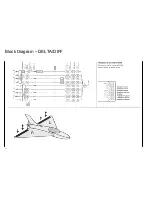
Page 12: ...Block Diagram DELTA DIFF 12...
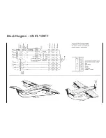
Page 13: ...Block Diagram UNIFLY DIFF 13...
Page 14: ...Block Diagram Quadro Flap 14...
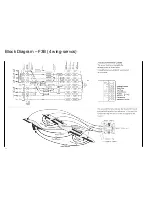
Page 15: ...Block Diagram F3B 3 wing servos 15...

