Programming Examples
for Fixed-Wing Models
46
5.) Defining Stick Allocation
Set the control stick allocation you are accustomed to
by entering:
5
7
ENTER
Thereupon the lower line of the display will read:
MODE 1
Now press one of the keys
1
…
4
, to suit your
normal control mode:
1
= Throttle and Ailerons on the right
Elevator and Rudder on the left
2
= Throttle and Rudder on the left
Ailerons and Elevator on the right
3
= Throttle and Rudder on the right
Ailerons and Elevator on the left
4
= Throttle and Ailerons on the left
Elevator and Rudder on the right
The figure on the display will change accordingly.
Terminate the input by pressing the
ENTER
key and
you are once again back in command mode.
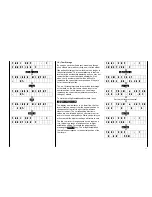
T A X I C U P : 1
F U N C T I O N ?
5
7
ENTER
↓↓
T A X I C U P : 1
M O D E 1
2
↓↓
T A X I C U P : 1
M O D E 2
ENTER
↓↓
T A X I C U P : 1
F U N C T I O N ?
6.) Defining the Model Type
The previous inputs were universally applicable to all
types of
model. Now you select the type of model to which
your actual model corresponds. For this example it is
assumed that you own a perfectly normal power
model, the ailerons of which as well as elevator and
rudder are operated by a single servo each. Input:
5
8
ENTER
In the lower line of the display now appears the actual
model type. At the moment it will reads “NORMAL”.
As you do not intend to switch to another model,
leave type selection by pressing the
ENTER
key.
Summary of Contents for mc-18
Page 1: ...1...
Page 10: ...Block Diagram NORMAL 10...
Page 11: ...Block Diagram NORMAL DIFF 11...
Page 12: ...Block Diagram DELTA DIFF 12...
Page 13: ...Block Diagram UNIFLY DIFF 13...
Page 14: ...Block Diagram Quadro Flap 14...
Page 15: ...Block Diagram F3B 3 wing servos 15...


