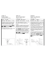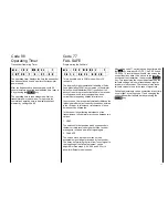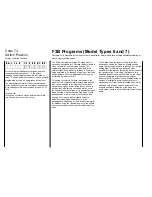
Code 51, 33, 61 and 71
Free Program Mixer
Programming Mixers and Dummy Mixers
30
In addition to the available mix and coupling
functions, all model programs provide a number of
freely programmable mixers. In the case of type 1 - 3
models nine mixers are at the disposal of the user,
types 4 and 5 have four mixers available, for F3B
types 6 and 7 a total of seven, and for the helicopter
types 8 and 9 there are four mixers available.
The mixers link an input signal to an outlet signal, with
allocation performed by code 51. As any optional
control function can be fed as an inlet signal, the
outlet signal affects any desired control channel, not a
control function. Distinguishing between these two
terms is of utmost importance. Control function refers
to the outlet signal of an operating element, that is a
stick with or without trim, slider, rotary control or a
channel switch, which in the course of the ensuing
action passes through all the mix and coupling
functions of the model program. A control channel is
the outlet signal for a specific receiver connection,
which until it arrives at the servo can only be affected
by throw adjust, neutral point adjust, throw reduction
or control surface reversing.
Mixers may also be switched in series for special
applications, which is say that in addition to the
control function proper all other preceding mixers can
also be used as inlet functions. All F3B mixers (see
F3B programs) and all freely programmable mixers
with a lower number are considered as preceding
mixers.
To give you an idea, imagine that instead of a control
function (see above) the outlet signal of a control
channel is used as the input function of the mixer
before it passes through throw adjust, neutral point
adjust, throw reduction or servo reversing.
Each of the freely programmable mixers can be
turned on and off by one of the switches allocated
using code 33.
Vital parameters of the mixers are the mix quotas
which determine how strongly the inlet signal affects
the control channel wired to the outlet of the mixer.
They also set the direction of the mixed signal and the
neutral point of the mixer, that is the point on the
control characteristic curve of the inlet signal where
the mixer does not affect the control channel wired to
the outlet (normally this will be the neutral point of the
control stick).
In the case of freely programmable mixers, these
parameters can be adjusted over a wide range. The
neutral point can be shifted to any desired point of the
control throw of the operating element wired to the
inlet (the distance from neutral point is called the
OFFSET). The mixing ratios can also be adjusted in
both directions above and below the neutral point,
either in symmetrical (code 61) or asymmetrical
(code 71) fashion. The mix direction can also be set
for both sides using codes 61 and 71 by setting the
values as + or -.
As a single control function can serve as inlet for an
optional number of mixers, and any number of mixers
may affect a control channel, the freely programmable
mixers permit achievement of special, highly complex,
applications.
DUMMY Mixer:
A so called dummy function may also be allocated as
an inlet signal, that is a control function that is not
available as a true operating element, but provides a
consistent control signal. In this manner it is possible
to make use of a control channel as an operating
element by allocating a dummy mixer and having the
outlet of the mixer affect the channel concerned.
Throw of the switch is then adjusted by the mix quota
and mix direction of the dummy mixer. A dummy
mixer also permits mixing an additional constant trim
signal dependent on a switch allocated by code 33.
Practical Example of a Dummy Mixer
An external switch is wired to socket 1, switches a
servo connected to receiver output 8,for example
operating a glider tug release device.
Programming Sequence:
1. Reset mixer from 0 to 8 via code 51. Inlet function
0 is obtained by pressing the
INC
key.
2. Input mix quota and direction via codes 61 and
71.
3. Allocate external switch to socket 1 via code 33.
Summary of Contents for mc-18
Page 1: ...1...
Page 10: ...Block Diagram NORMAL 10...
Page 11: ...Block Diagram NORMAL DIFF 11...
Page 12: ...Block Diagram DELTA DIFF 12...
Page 13: ...Block Diagram UNIFLY DIFF 13...
Page 14: ...Block Diagram Quadro Flap 14...
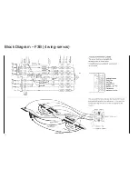
Page 15: ...Block Diagram F3B 3 wing servos 15...

