9
Assembling the mechanics
The turbine helicopter mechanics system is intended for installation in a suitable separately
available GRP fuselage designed expressly for this application. For safety reasons we strongly
advise against installing the system in a fuselage not designed for turbine mechanics.
You will also need a separately available stainless steel exhaust duct to suit the fuselage kit you
are using; the turbine exhaust gas is routed out of the fuselage through this duct.
The main mechanical assembly is supplied factory-built, with the turbine already installed; the
components required to install the swashplate servos, the bellcranks and the swashplate are
supplied as a kit of parts.
The kit also includes the main rotor head and tail rotor.
The auxiliary turbine equipment, i.e. fuel pump, valves (gas, kerosene) and filters are already
installed in the mechanics, and the hose connections are in place as standard. On the right of
the mechanics is a hose connection for the fueltank, on the left a hose connection for the aux-
iliary gas tank. The electrical connections are grouped together in an interface box, from which a
wiring loom (with connector fitted) runs to the ECU. The loom can simply be unplugged, which
considerably simplifies the task of installing and removing the mechanics.
1. Completing the main mechanics
The chassis of the main mechanics is supplied pre-assembled, with the turbine installed. Com-
pleting the assembly stage requires the installation of the swashplate, the swashplate servos
and the bellcranks.
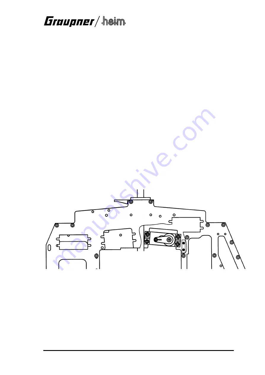
1.1 Installing the front pitch-axis / collective pitch servo
(bagJ2-3)
The front pitch-axis / collective pitch servo is installed in the left-hand chassis side frame
from
the inside
using M3 x 12 socket-head cap screws, washers and self-locking nuts. The cable
exit must
face forward
. Fix a linkage ball
on the
top
of a suitable servo output arm, 20 mm
from the pivot axis, using an M2 x 8 screw and nut; fit the output arm on the servo in such a way
that it is exactly horizontal and facing aft when the servo is at centre.
1.2 Installing the rear pitch-axis / collective pitch servo
(bag J2-3)
The rear pitch-axis / collective pitch servo is installed in the opening in the right-hand chassis
side frame
from the inside
, using M3 x 12 socket-head cap screws, washers and self-locking
nuts, with the cable exit
facing aft
. Fix a linkage ball
on the top
of a suitable servo output arm,
20 mm from the pivot axis, using an M2 x 8 screw and nut; fit the output arm on the servo in
such a way that it is exactly horizontal and facing forward when the servo is at centre.


