


3-
14
750/760 Feeder Management Relay
GE Power Management
3.2 TYPICAL WIRING
3 INSTALLATION
3
When the
BREAKER STATE BYPASS
setpoints are enabled, the trip and close coil supervision circuits can be
arranged to monitor the trip and close circuits continuously, unaffected by breaker state. This application
requires that an alternate path around the 52a or 52b contacts in series with the operating coils be provided,
with modifications to the standard wiring as shown on drawing 818730. With these connections, trickle current
can flow at all times. If access to the breaker coil is available, as shown in drawing A above, continuous coil
monitoring regardless of breaker state is possible without using a resistor to bypass the 52a/b contact.
3.2.12 SOLID STATE TRIP OUTPUT
A high speed solid state (SCR) output is also provided. This output is intended for applications where it is
required to key a communications channel.
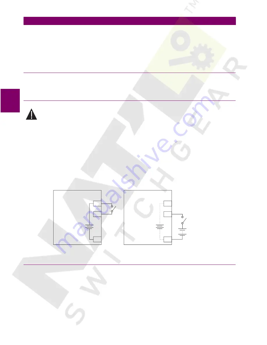
3.2.13 LOGIC INPUTS
Ensure correct polarity on logic input connections and do not connect any logic input circuits
to ground or else relay hardware may be damaged.
External contacts can be connected to the relay’s 14 logic inputs. As shown, these contacts can be either dry
or wet. It is also possible to use a combination of both contact types.
A dry contact has one side connected to terminal C12. This is the +32 VDC voltage rail. The other side of the
dry contact is connected to the required logic input terminal. When a dry contact closes, a current of approxi-
mately 2 mA will flow through the associated circuit.
A wet contact has one side connected to the positive terminal of an external DC power supply. The other side
of this contact is connected to the required logic input terminal. In addition, the negative side of the external
source must be connected to the relay’s DC NEGATIVE rail at terminal D12. The maximum external source
voltage for this arrangement is 300 V DC.
Figure 3–17: DRY AND WET CONTACT CONNECTIONS
3.2.14 ANALOG INPUT
Terminals A1 (+) and A2 (–) are provided for the input of a current signal from a wide variety of transducer out-
puts - refer to technical specifications for complete listing. This current signal can represent any external quan-
tity, such as transformer winding temperature, bus voltage, battery voltage, station service voltage, or
transformer tap position. Be sure to observe polarity markings for correct operation. Both terminals are
clamped to within 36 volts of ground with surge protection. As such, common mode voltages should not
exceed this limit. Shielded wire, with only one end of the shield grounded, is recommended to minimize noise
effects.
CAUTION
C12
C12
C1
C1
D12
D12
32 Vdc
32 Vdc
+32 VDC
+32 VDC
LOGIC INPUT 1
LOGIC INPUT 1
DC NEGATIVE
DC NEGATIVE
SR RELAY
SR RELAY
30-300 Vdc
Dry Contact Connection
Wet Contact Connection
LOGICIN.CDR
Summary of Contents for 750
Page 2: ......
Page 4: ......
Page 124: ...8 14 750 760 Feeder Management Relay GE Power Management 8 12 INSTALLATION 8 S1 RELAY SETUP 8 ...
Page 488: ...A 4 750 760 Feeder Management Relay GE Power Management A 1 FIGURES AND TABLES APPENDIXA A ...
Page 492: ...C 2 750 760 Feeder Management Relay GE Power Management C 1 WARRANTY INFORMATION APPENDIXC C ...
Page 502: ...x 750 760 Feeder Management Relay GE Power Management INDEX ...
Page 503: ...GE Power Management 750 760 Feeder Management Relay NOTES ...


