background image

Ranger HRC™ operator´s manual – Hardware installation

Publ. No. TM 614 006 699 Rev B – ENGLISH (EN) – Oct 30. 2008 


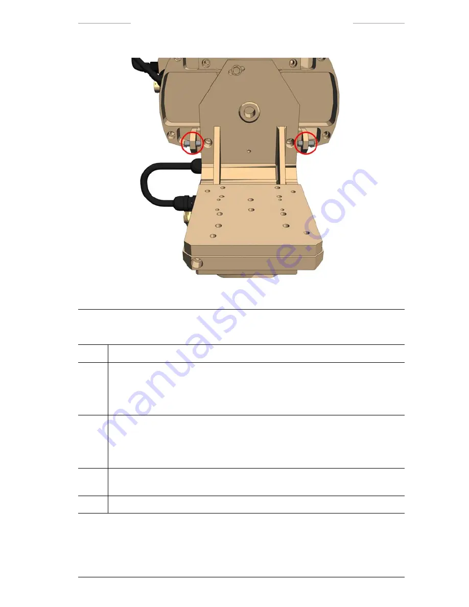
Figure 9.16 Elevation adjustment screws

Elevation adjustment

Step

Action

1

Loosen the two hexagon head bolts a bit, see Figure 9.14 and Figure 9.15.

2 a

Raise the IR Camer

a by loosening the rear elevation adjustment screw and tighten the 

front screw, see Figure 9.16.

Lower the IR Camera

 by loosening the front elevation adjustment screw and tighten the 

rear elevation adjustment screw.

2 b

Raise the TV Camera

 by loosening the front elevation adjustment screw and tighten the 

rear screw, see Figure 9.16.

Lower the TV Camera

 by loosening the rear elevation adjustment screw and tighten the 

front elevation adjustment screw.

3

When the position of the camera is correct, tighten the two hexagon head bolts, see 

Figure 9.14 and Figure 9.15.

4

Tighten the two elevation adjustment screws, see Figure 9.16.

Summary of Contents for Ranger HRC MS

Page 1: ...Publ No TM 614 006 699 Rev B ENGLISH EN Oct 30 2008 Ranger HRC MS Operator s manual iii...

Page 2: ...ess for a particular purpose FLIR Systems shall not be liable for any direct indirect special incidental or consequential loss or dam age whether based on contract tort or any other legal theory Copyr...

Page 3: ...ntrol Unit 16 3 2 7 Remote Power Controller 17 3 3 System control 17 System Configurations 18 Functions and features 22 5 1 Operating modes 22 5 1 1 NORMAL mode 22 5 1 2 AUTOSCAN mode 22 5 1 3 PARK mo...

Page 4: ...menu 56 7 5 1 Image menu when IR is selected 56 7 5 1 1 Man level span 58 7 5 2 Image menu when TV is selected 59 7 6 Setup menu 60 7 6 1 Setup menu when IR is selected 60 7 6 1 1 Setup Image 61 7 6 1...

Page 5: ...lt 105 9 1 3 IR and TV Camera 106 9 2 Cable connections 108 9 2 1 Pan Tilt unit 109 9 2 2 System components 110 9 2 2 1 JPC2 configuration 111 9 2 2 2 Junction Box configuration 112 9 2 2 3 Power Box...

Page 6: ...4 2 3 Speed and Dwell settings 146 11 4 2 4 Creating autoscan lists and Appending autoscan points 147 11 4 2 5 Editing autoscan points settings and Moving autoscan points 148 11 4 2 6 Route sequence 1...

Page 7: ...an and DDE mode 179 12 2 7 2 Adjustments in Auto Level mode 179 12 2 7 3 Adjustment in Manual mode 180 12 2 8 Color Distribution 180 12 2 9 DDE Control 181 12 2 10 Filter 182 12 2 11 Palette 183 12 2...

Page 8: ...nector 202 15 5 1 7 J16 10 pin connector 203 15 5 2 Pin configuration Joystick Control Unit JCU 204 15 5 2 1 J10 23 pin connector 204 15 5 3 Pin configuration JB 205 15 5 3 1 J4 6 pin connector 205 15...

Page 9: ...imaging 236 17 1 Introduction 236 17 2 The electromagnetic spectrum 236 17 3 Blackbody radiation 237 17 3 1 Planck s law 238 17 3 2 Wien s displacement law 240 17 3 3 Stefan Boltzmann s law 241 17 3...

Page 10: ......

Page 11: ...er HRC MS system offers the following main features Cooled thermal detector for long range performance designed for man size target detection above 10 km and vehicle detection above 20 km Large format...

Page 12: ...onal awareness in the wide field of view while maintaining detailed recog nition capabilities in the narrow field of view By seeing further and being able to recognizing more details the operator can...

Page 13: ...pad for more than 3 seconds to manually enable the pan tilt When using a Laser When using a system equipped with the optional Laser be sure and read the Laser Warning Label sample below Do not open th...

Page 14: ...iew capabilities For detailed technical data of the cameras and sensors see section 15 1 3 1 1 IR Camera The IR Camera is equipped with a cooled mid wave detector which offers long range performance i...

Page 15: ...ional system component The LRF unit is a light weight eye safe laser range finder radiating in the 1 54 m Erbium glass wave length The unit consists of a laser trans mitter a laser receiver power supp...

Page 16: ...imensions The intention is to measure the geo magnetic field in order to find magnetic north However also other mag netic fields near the DMC unit will be included in the result and have effect on the...

Page 17: ...t numbers of the cables please refer to the Parts list in section 15 2 For an overview of the location of the connectors see section 15 4 3 2 1 Pan Tilt The Pan Tilt unit is a rugged two axis pan and...

Page 18: ...to the X2 connector on the Pan Tilt unit and to the IR Camera 3 GPS antenna cable The GPS antenna cable is connected to the X4 connector on the Pan Tilt unit and to the GPS unit 4 DMC cable The DMC i...

Page 19: ...lled from a remotely located Joystick Control Unit the System cable is connected to the JCU connector J1 on the JPC2 unit and to the J5 connector on the Junction Box or the J5 connector on the Power B...

Page 20: ...et cable The Ethernet cable is used to connect a LAN switch in an IP network to the JPC2 unit The Ethernet cable is connected to the IP connector J14 on the JPC2 unit NOTE The maximum cable distance b...

Page 21: ...dard set of features such as video output buffers and host communication signal conditioning Figure 3 3 Junction Box connections front side Junction Box connections front side Callout Description 1 Re...

Page 22: ...video monitor NOTE The J7 connector corresponds to the VIDEO 2 connector J11 on the JPC2 unit Figure 3 4 Junction box connections rear side Junction Box connections rear side Callout Description 1 Sys...

Page 23: ...nction Box or directly to the JPC2 unit Figure 3 5 Power Supply connections Power Supply connections Callout Description 1 Power cable The Power cable is connected to the Power Supply unit and to the...

Page 24: ...from an external computer The Host cable is connected to the J8 connector on the Power Box 2 Video cable The Video cable is connected to the J7 connector on the Power Box and to an external video moni...

Page 25: ...wer Box and to an external video monitor NOTE The J6 connector corresponds to the VIDEO 2 connector J11 on the JPC2 unit 6 AC Mains cable The AC Mains cable is connected to the power inlet on the Powe...

Page 26: ...zimuth and elevation position With the keypad buttons frequently used functions are quickly executed The JCU is also used to navigate in the menu system of the System Software For more information abo...

Page 27: ...tand alone operation or for operation in an IP network with multiple systems With the stand alone configuration the system is controlled via the System Software run ning on the JPC2 unit With the IP n...

Page 28: ...R cameras Ranger HRC U Ranger HRC S TV cameras LR TV UR TV SR TV Sensors Laser Range Finder LRF Digital Magnetic Compass DMC GPS System components JPC2 Pan Tilt For detailed technical data of the came...

Page 29: ...operator s manual System Configurations Publ No TM 614 006 699 Rev B ENGLISH EN Oct 30 2008 19 Figure 4 2 Ranger HRC U UR TV LRF DMC GPS JPC2 and Pan Tilt Figure 4 3 Ranger HRC U SR TV DMC GPS JPC2 an...

Page 30: ...erator s manual System Configurations 20 Publ No TM 614 006 699 Rev B ENGLISH EN Oct 30 2008 Figure 4 4 Ranger HRC S LR TV LRF DMC GPS JPC2 and Pan Tilt Figure 4 5 Ranger HRC S UR TV LRF DMC GPS JPC2...

Page 31: ...Ranger HRC operator s manual System Configurations Publ No TM 614 006 699 Rev B ENGLISH EN Oct 30 2008 21 Figure 4 6 Ranger HRC S SR TV DMC GPS JPC2 and Pan Tilt...

Page 32: ...to pan and tilt the system to move the system to the preset field of views to zoom in and out to focus etc 5 1 2 AUTOSCAN mode In AUTOSCAN mode the system is automatically moved from point to point in...

Page 33: ...c Com pass DMC or a specific target such as a gateway or an entrance door For instructions on how to define the home position see section 10 3 When the system is in the mechanical home position the ca...

Page 34: ...left corner of the monitor 5 1 5 MENU mode When the system is in MENU mode the menu system of the System Soft ware is displayed which gives access to the features of the system The JCU is used to nav...

Page 35: ...er the lens cover External shutter or the scene Shutter off is used as thermal reference The normal procedure is to start with an Internal NUC If an acceptable image quality is not achieved an Externa...

Page 36: ...tor s manual Functions and features 26 Publ No TM 614 006 699 Rev B ENGLISH EN Oct 30 2008 Figure 5 1 Adjust Area 1 Figure 5 3 Adjust Area 2 Figure 5 2 Adjust Area 3 Figure 5 4 Adjust Area 4 Figure 5...

Page 37: ...age quality but in scenes with low or high contrast DDE and or Manual mode may be better 5 2 4 Adjust image Adjust image is a feature that allows manual adjustments of the image with regards to level...

Page 38: ...ay be better The Linear mode also gives a more intui tive perception of the temperature contents 5 2 6 Digital Detail Enhancement Digital Detail Enhancement DDE is a function that enhances the visibi...

Page 39: ...rated from the control of the dynamic range of the background The filter operates as a powerful noise filter at one end and as very strong detail enhancing filter at the other end The DDE Control feat...

Page 40: ...taste In low contrast scenes for example in rainy and foggy weather a low DDE Control value is recommended 0 20 In high contrast scenes for example a sunny day in the desert a high DDE Control value...

Page 41: ...Filter shall be set to Low or High to improve the image Filtering is normally not suitable for moving targets as it may cause smear ing in the image presentation 5 2 9 IR palette There are four diffe...

Page 42: ...timate values between known point observations The camera software interpolates the resolu tion by mathematically analyzing what would be the most plausible value of the closest neighbor of a pixel Zo...

Page 43: ...it are the joystick with a rota ting collar and a push button and the keypad with push buttons All but tons are back lit for operator convenience There is also a control for the backlight and two LED...

Page 44: ...indicator is lit 13 PRK button 14 Navigation keypad 15 FRZ button 16 ENTER button 6 2 Joystick and keypad buttons The functions of the joystick and the keypad buttons depend on the sys tem mode The f...

Page 45: ...etween Slave mode on off see section 7 5 1 FCN Button FCN is used together with other buttons to provide additional functionality SCN Press the SCN button to enter AUTOSCAN mode If there are no autosc...

Page 46: ...DDE value Press and hold down the button to decrease the DDE value If the adjustment mode is set to AUTO linear of full or MANUAL the and buttons have no function Press and hold down the FCN buttons...

Page 47: ...n 1 second to perform a one shot auto focus adjustment Press the FCN NUC buttons 1 second to perform an External NUC against the lens cover Press the FCN NUC buttons 1 second to go to the fixed focus...

Page 48: ...disabled in the Setup Pan Tilt dialog box see section 7 6 1 3 FRZ Press the FRZ button to freeze unfreeze the image ENTER No function in AUTOSCAN mode 6 2 3 PARK mode The PARK mode is entered by press...

Page 49: ...o deactivate the LRF unit and exit the LRF mode NUC Press the NUC button 1 second to perform an Internal NUC Press the NUC button 1 second to perform a one shot auto focus adjustment Press the FCN NUC...

Page 50: ...the MENU mode open the dialog box of the highlighted feature activate the highlighted feature and exit MENU mode C CANCEL Use the CANCEL button to exit the active dialog box exit MENU mode without ch...

Page 51: ...de is entered by pressing the FCN button in AUTOSCAN mode The PROG POSITION mode can also be entered from the System Software menu system NOTE For full functionality of the JCU when programming autosc...

Page 52: ...be inverted in the Setup Image dialog box see section 7 6 1 1 PRK Press the PRK button 1 second to send the system to the home position If the PRK button is pressed 1 second again when the system is...

Page 53: ...re also provides the operator with information about the system This chapter describes features available in the System Software version 1 4 5 7 1 System information System information is displayed on...

Page 54: ...rence position entered in the Setup Pan Tilt dialog box see section 7 6 1 3 8 The Digital elevation indicator provides a numeric readout of the system s elevation 9 The Analog elevation indicator prov...

Page 55: ...the center of the monitor The following status texts are available Zooming in Zooming out Focus far Focus near Frozen Autoscan Adjusting Connecting Saving Laser ready 6 Searching GPS Parked Slave Mode...

Page 56: ...hat different depending on if IR or TV is selected Figure 7 2 Menu bar with Pan Tilt menu selected Features that directly perform an action are displayed as a command for example Start autoscan in the...

Page 57: ...toscan point the system shall be moved to Figure 7 3 Pan Tilt menu and Go to position dialog box Example Step Action 1 Press the ENTER button to enter MENU mode 2 Use the LEFT RIGHT navigation buttons...

Page 58: ...the monitor Setup The Setup menu is used to define system constants and the appearance of the system information indicators GPS The GPS menu is used to control the GPS unit LRF The LRF menu is used t...

Page 59: ...e is used to move the system as fast as possible to the previous point in the currently active scan routine Go to position The Go to position feature opens the Go to position dialog box see section 7...

Page 60: ...n point 7 4 1 2 Current position list The Current position list dialog box is used to append autoscan points to the current autoscan list and to define new autoscan lists If no current position list e...

Page 61: ...lists and Appending autoscan points see section 11 4 2 4 Figure 7 8 New pos dialog box New pos dialog box Feature Description Speed The Speed feature is used to select the rate with which the system...

Page 62: ...ng autoscan points see section 11 4 2 5 Figure 7 9 Edit pos dialog box Edit pos dialog box Feature Description Speed The Speed feature is used to select the rate with which the system shall move to ne...

Page 63: ...ging the route sequence is described in section 11 4 2 6 Inactive The Inactive item displays the inactive autoscan points and is used to activate deactivate autoscan points The procedure for activatin...

Page 64: ...h the list name dis played in the List no item Recall Recalls and loads the autoscan list with the list name displayed in the List no item Delete Deletes the autoscan list with the list name displayed...

Page 65: ...as possible to the next point in the currently active scan routine Go to previous The Go to previous feature is used to move the system as fast as possible to the previous point in the currently activ...

Page 66: ...somewhat different depending on if IR or TV is selected 7 5 1 Image menu when IR is selected Figure 7 13 Image menu when IR is selected NOTE For features with on off alternatives the displayed feature...

Page 67: ...d to cycle trough the IR palette options Gray Rainbow Rainbow HC Iron NOTE The IR palette can also be changed in the Setup menu see section 7 6 1 1 Freeze Live The Freeze Live feature is used to chang...

Page 68: ...ick is moved The Defrost feature is only enabled at freezing ambient temperature Power on off The Power on off feature is used to turn on off the IR camera When the IR camera is turned off a colored i...

Page 69: ...ture Description Declutter The Declutter feature is used to temporarily remove the system information from the monitor When the ENTER button is pressed the system informa tion is shown again Auto focu...

Page 70: ...he TV camera is turned off a colored image is displayed on the monitor and all features in the Image menu except Power on are disabled Slave mode on off The Slave mode on off feature is used to activa...

Page 71: ...era see chapter 8 To exit the IR Camera menu system press the CANCEL button If not in use for a while the IR Camera menu system is automatically exited Local adapt The Local adapt feature opens the Se...

Page 72: ...togram mode DDE linear Automatic adjustment of level and span with Digital Detail Enhancement and Color Distribution in Linear mode DDE full Automatic adjustment of level and span with Digital Detail...

Page 73: ...adjustment Press the C NUC buttons 1 second to perform an External NUC against the scene Adjust DDE The Adjust DDE feature is used to adjust the DDE Control value Yes Opens the DDE dialog box see sec...

Page 74: ...box Feature Description Data field The Data field feature is used to control the appearance of the two lines of system information that is presented at the bottom of the monitor Normal Both lines of...

Page 75: ...focus position indicator On The focus position indicator is always shown Off The focus position indicator is always hidden When changed The focus position indicator is only shown when the focus is cha...

Page 76: ...ystem software graphics This setting keeps as much as possible of the video image free from overlaid information However many monitors cut the video image close to the edges With such a monitor some o...

Page 77: ...Fast The autoscan speed is the speed with which the system moves to the next autoscan point The Slow Normal and Fast values are adjustable from 0 1 s to 70 s pan and from 0 1 s to 30 s tilt both in 0...

Page 78: ...wards P T Speed relative zoom The P T Speed relative zoom feature is used to control the speed of the Pan Tilt unit in relation to the current field of view On The panning and tilting speeds are lower...

Page 79: ...he same for IR and TV Figure 7 22 Setup Local adapt dialog box Setup Local adapt dialog box Feature Description Language The Language feature is used to select the system language English is the defau...

Page 80: ...on Year The Year feature is used to set the year 2003 2038 Month The Month feature is use to set the month 01 12 Day The Day feature is use to set the day 01 31 Hour The Hour feature is used to set th...

Page 81: ...me for IR and TV Figure 7 24 Setup Maintenance dialog box If a password other than the default system value 0000 has been set the Enter password dialog box will appear before the Setup Maintenance dia...

Page 82: ...col see the Protocol feature below is selected the Device ID feature is disabled Protocol The Protocol feature is used to select the type of communication protocol 5x0 TASS Optional protocols such as...

Page 83: ...ult setting feature is used to reset parameters except for example lists of autoscan points Baudrate and Protocol to factory settings Yes The default settings are reset No No action Detect devices The...

Page 84: ...opened if a password other than the default system value 0000 has been set Figure 7 25 Enter password dialog box Enter password dialog box Feature Description Enter password The Enter password feature...

Page 85: ...Figure 5 27 New password dialog box 7 6 1 6 3 Change password The Change password dialog box is used to change an existing pass word Figure 7 28 Change password 7 6 1 6 4 Detect devices The Detect de...

Page 86: ...nformation dialog box is the same for IR and TV Figure 7 30 System information dialog box System information dialog box Feature Description Video mode The Video mode item displays the type of video mo...

Page 87: ...gy feature opens the Setup Symbology dialog box see section 7 6 2 2 Pan tilt The Pan tilt feature opens the Setup Pan tilt dialog box see section 7 6 1 3 Local adapt The Local adapt feature opens the...

Page 88: ...if the object is very dark the backlight will increase the image quality Image effect The Image effect feature is used to select Color or Black White mode Off Puts the TV camera in Color mode B W Put...

Page 89: ...enu NOTE For features with on off alternatives the displayed feature for example Power off is the action that will be performed if the feature is selected and not the current status For example Power...

Page 90: ...ted the text Laser ready 6 is displayed in the upper left corner of the monitor In LRF mode most buttons are disabled Press button C to deactivate the LRF unit and to exit the LRF mode Calib cross On...

Page 91: ...ature is disabled until the Pan Tilt unit is activated which is done when the PRK button is pressed 3 seconds Power on off The Power on off feature is used to turn the DMC unit on off When the DMC uni...

Page 92: ...ue north correction The True north correction feature is used to enter a known deviation between magnetic north and true north A negative number corrects towards west and a positive number towards eas...

Page 93: ...the IR image that are avail able via the System Software menu system and the Joystick Control Unit JCU are fully sufficient see section 11 3 8 1 IR Camera information Information from the IR Camera ca...

Page 94: ...or distribution mode 6 Top line status indicator WHITE or BLACK polarity selection i e white hot or black hot 7 Focus position indicator Indicates the present focus position Focusing against infinity...

Page 95: ...Camera menu and feature highlighted is displayed Features that directly perform an action are displayed as a command for example NUC Features that open up a dialog box are displayed with three dots a...

Page 96: ...access these sub menus without entering an access code 8 3 1 Image menu Figure 8 2 Image menu Menu choice Possible choices Explanation Zoom in Zoom out The camera has four fixed zoom positions Press t...

Page 97: ...and then press the navigation pad left right To change the zoom speed 0 100 select Speed and use the navigation pad to adjust the speed value Select the Digital Zoom button and press the ENTER to sho...

Page 98: ...the Fix button and press the navigation pad left right To leave the dialog box press ENTER NUC Press the ENTER button to make the camera perform a NUC i e a non uniformity correc tion The NUC function...

Page 99: ...st image and press ENTER to display the Adjust image dialog box In this dialog box you can change level and span or the corresponding brightness and contrast The appearance of this dialog box depends...

Page 100: ...to select different IR palettes Press the ENTER button to confirm Invert Palette Press the ENTER button to invert the current palette Hide graphics Show graphics When graphics are hidden this command...

Page 101: ...st in the camera s internal file system Directories Use the navigation pad to browse the directories in the camera s internal file system Delete image Press the ENTER button to delete an image 8 3 3 S...

Page 102: ...profile With DDE such objects are brought forward and thus still visible to the degree set by the selected DDE level NOTE The most suitable settings for a certain imaging situation depends on many dif...

Page 103: ...sed during the camera calibration The image is calibrated against the actual scene at which the camera is looking This method allows for calibration against surfaces with a representative temperature...

Page 104: ...TER button and use the naviga tion pad to select what area the camera should use when adjusting the image with regards to level and span Focus area A1 A2 A3 Press the ENTER button and use the naviga t...

Page 105: ...d to display or hide the bottom status line Press the ENTER button to confirm Temp range On Off Use the navigation pad to display or hide the bottom status line Press the ENTER button to confirm FLIR...

Page 106: ...gorithm named after the commit tee that defined it Use this file format when no or a third party software will be used for image post processing FFF FLIR File Format FLIR Systems propriety file format...

Page 107: ...e ENTER button to confirm Day 1 thru 31 Day Change the day by pressing the navigation pad left right Press the ENTER button to confirm Hour 1 thru 24 Hour Change the hour by pressing the navigation pa...

Page 108: ...R button to confirm NOTE The change will take effect and the graphical user interface will be restarted when pressing the ENTER button Temp unit C F Use the navigation pad to select degrees Celsius or...

Page 109: ...ENTER button Video color On Off Auto Us the navigation pad to select video color should be enabled disabled or set to Auto If Auto is selected the camera will automatically enable video color if a col...

Page 110: ...ne packet at the same time as receiving the data of the second packet This means that the client software does not need to download an entire file before playing the data Menu choice Possible choices...

Page 111: ...settings By selecting Save settings the current system settings will be saved and loaded when the camera is switched on the next time 8 3 3 12 Factory default By selecting Factory default all camera...

Page 112: ...2 Ext Shutter On Ext Shutter Off By selecting Ext Shutter On the external shutter is moved to cover the front lens When external shutter is on the menu selection will be Ext Shutter Off To remove the...

Page 113: ...log When you select BIT Start the camera performs a number of built in tests This log file displays the results of those tests 8 3 4 6 BIT start Figure 8 17 Start BIT dialog box Select BIT start and...

Page 114: ...Test image and press the ENTER button You can use this image test pattern to calibrate your video moni tor or computer screen Depending on the settings in the System Setup dialog box this image test p...

Page 115: ...delivered NOTE Do not over torque when tightening screws max 10 Nm 9 1 1 JPC2 Ranger HRC MS is a high performance surveillance system including a very small field of view optical device It is importan...

Page 116: ...side as the connectors on the JPC2 unit 2 Tighten the four M8 x 20 screws Figure 9 1 item 1 9 1 3 IR and TV Camera The Pan Tilt unit is equipped with a left and a right mounting plate whe re the IR a...

Page 117: ...s Mounting the cameras Step Action 1 Fit the cameras in place one at the time on the mounting plates using the two guiding pins It is easiest to start with the front guiding pin and then fit the rear...

Page 118: ...rotective caps when not in use For connections with bayonet sockets the connector shall be fastened un til it is locked a click sound is heard For sockets with a color marking the connectors shall be...

Page 119: ...nections Pan Tilt connections Callout Denomination Part number Connections 1 TV Camera cable 614 007 038 G007 858 G007 712 From X3 connector on Pan Tilt to TV Camera 2 IR Camera cable G007 678 From X2...

Page 120: ...network with multiple systems Cable con nections for three typical stand alone configurations are described in the sections below NOTE The control of the video channels TV and IR is defined via a sett...

Page 121: ...2 configuration JPC2 configuration Callout Denomination Part number Connections 1 AC Mains cable From AC mains supply to Power Supply 2 Power cable 194 628 From POWER connector J2 on JPC2 to Power Sup...

Page 122: ...N Oct 30 2008 9 2 2 2 Junction Box configuration With this configuration the Junction Box is used for connections of the JCU Power Supply unit and monitors The system is controlled and powered via the...

Page 123: ...to Power Supply 3 Video cable 908 929 From J6 connector on Junction Box to monitor NOTE If only one monitor is used it shall be connected to the J6 connector 4 Video cable 908 929 From J7 connector on...

Page 124: ...2 3 Power Box configuration With this configuration the Power Box is used for connections of the JCU and monitors The system is controlled and powered via the single Sys tem Cable connected to the JP...

Page 125: ...able 908 929 From J7 connector on Power Box to monitor NOTE If only one monitor is used it shall be con nected to the J7 connector 3 Video cable 908 929 From J6 connector on Power Box to monitor 4 JCU...

Page 126: ...sted if needed 9 3 1 Alignment method The alignment method depends on the equipment that has been repla ced If one camera is replaced the other camera is used as reference If both cameras are replaced...

Page 127: ...system towards the alignment object 3 Use the optical zoom and zoom in maximally see section 11 2 Do not use the digital zoom 4 Use the joystick and move the system until the center of the crosshair r...

Page 128: ...ast 800 m or more depending on visibility In order to determine where the LRF unit is aiming distant measure ments are made closer and closer to the alignment object until the object is hit as illustr...

Page 129: ...the crosshair reticle is in the middle of the laser lobe as shown in the right part of Figure 9 9 9 Use the joystick to direct the system to the other side of the alignment object see figure 9 10 10...

Page 130: ...evation adjustments may be needed before the elevation alignment is correct 17 Verify that the azimuth alignment is still correct If not repeat the distance measurements from the sides and azimuth adj...

Page 131: ...ws that are marked with rings in Figure 9 13 a bit 2 Adjust the camera position with the azimuth adjustment screw which is marked with an arrow in Figure 9 13 Loosen the screw to turn the camera towar...

Page 132: ...Ranger HRC operator s manual Hardware installation 122 Publ No TM 614 006 699 Rev B ENGLISH EN Oct 30 2008 9 3 4 2 Elevation adjustment Figure 9 14 Hexagon head bolt Figure 9 15 Hexagon head bolt...

Page 133: ...screw see Figure 9 16 Lower the IR Camera by loosening the front elevation adjustment screw and tighten the rear elevation adjustment screw 2 b Raise the TV Camera by loosening the front elevation adj...

Page 134: ...one monitor is used the recommended IR TV video swap setting is YES With this setting the currently active video channel IR or TV is always displayed on the video monitor In this case the TV IR button...

Page 135: ...k Control Unit settings The functionality of the Joystick Control Unit JCU depends to some ex tent on settings in the System Software 10 2 1 Original or Alternative setting The JCU operates with two d...

Page 136: ...NUC buttons 1 second to perform a one shot auto focus adjustment AF NUC Press button NUC 1 second to perform a one shot auto focus ad justment Press button NUC 1 second to perform an Internal NUC and...

Page 137: ...ystick towards himself the Pan Tilt unit will move downwards Pilot When the operator moves the joystick away from himself the Pan Tilt unit will move downwards The Joystick polarity feature is used to...

Page 138: ...nt This is the default setting Off The and buttons can not be used to move the system to the previous next autoscan point Autoscan point selection setting Step Action 1 Press the ENTER button to enter...

Page 139: ...the local magnetic declination between magnetic north and true north must be entered into the system before the DMC calibra tion is started A negative number corrects toward west and a positive number...

Page 140: ...Hold down the LEFT RIGHT button for a while to decrease increase the Azimuth value with larger increments 4 Press the ENTER button to start the calibration A search pattern is performed in order to f...

Page 141: ...home position to a specific target for ex ample a gateway or an entrance door Manual setting can also be used to manually set the home position to true north if the DMC calibration does not succeed In...

Page 142: ...o confirm and to exit the MENU mode 10 4 2 Slave mode The Slave mode feature is used to activate deactivate Slave mode When Slave mode is active changes in field of view will apply to both the IR and...

Page 143: ...he PRK button has to be pressed Save settings Step Action 1 Press the PRK button 1 second to save the system settings The system will be sent to the mechanical home position NOTE Do not turn off the s...

Page 144: ...urn on the system with the ON OFF switch on the Power Box or Power Supply unit 3 The red status indicator on the JCU flashes while the connection is being established A steady light indicates that the...

Page 145: ...n 1 Press the PRK button 1 second to send the system to the mechanical home position The system settings will automatically be saved NOTE Do not turn off the system while Saving is displayed on the mo...

Page 146: ...urned on otherwise it is not pos sible to use the remote power control function Remotely turning power on Step Action 1 Press and hold down the FCN button 2 While the FCN button is held down press and...

Page 147: ...tick collar to the left to zoom out Turn the joystick collar to the right to zoom in Auto focus Verify that the target is in the center of the image Keep the camera steady when auto focusing Press the...

Page 148: ...s near far Freeze alt 1 Press the FRZ button to toggle between live and frozen image Freeze alt 2 Press the ENTER button to enter MENU mode Select Freeze Live from the Image menu and press the ENTER b...

Page 149: ...l NUC the image is calibrated against a shutter inside the camera With External NUC either the lens cover or the scene is used as thermal reference The normal procedure is to start with an Internal NU...

Page 150: ...ce Press the C NUC buttons 1 second to perform an External NUC against the scene NOTE If the default setting for the NUC button has been changed Setup Image dialog box see section 7 6 1 1 the C NUC bu...

Page 151: ...TER button to enter MENU mode 2 Select Image from the Setup menu and press the ENTER button 3 Select Level Span 4 Use the LEFT RIGHT navigation buttons to select adjustment mode 5 Press the ENTER butt...

Page 152: ...OWN navigation buttons to decrease increase the width of the span 5 Press the ENTER button to confirm and exit the MENU mode 11 3 4 DDE adjustment DDE Digital Detail Enhancement is an adjustment mode...

Page 153: ...he DDE dialog box is displayed 5 Use the UP DOWN navigation buttons to increase decrease the DDE Control value 6 Press the ENTER button to confirm and to exit MENU mode 11 3 5 IR palette There are fou...

Page 154: ...he time that the system stays on the target the speed with which the system moves to next autoscan point the focus and the field of view for each autoscan point are fully programmable It is possible t...

Page 155: ...s and management of auto scan lists are available in the System Software menu system when IR is selected not when TV is selected Selecting IR Camera 1 Ensure that IR is selected If not press the TV IR...

Page 156: ...New pos and Edit pos dialog boxes as described in the sections below The Speed setting defines how fast the system shall move to next autoscan point The preset speed rates are defined in the Setup Pa...

Page 157: ...he system is now in PROG POSITION mode 4 a To create a new autoscan list use the LEFT RIGHT buttons to select New and press the ENTER button NOTE The currently active autoscan list will be deleted whe...

Page 158: ...e new desired position Use the JCU to make the desired adjustments of field of view and focus see section 11 4 2 2 Press the FCN button to register and save the position and the field of view focus an...

Page 159: ...LEFT RIGHT navigation buttons to move the point within the autoscan list 6 b Use the UP DOWN navigation buttons to move the point from active to inactive status or vice versa 7 a Press the FCN button...

Page 160: ...is already used the Overwrite list dialog box will be displayed Select Yes to overwrite the list and to exit MENU mode Select No to return to the Store recall position list dialog box When recalling...

Page 161: ...he rate is too high the system will block the LRF unit for a short recovery time The status text Laser charging 6 is displayed when the LRF unit is acti vated The number N is decremented after each sh...

Page 162: ...be within line of sight from the LRF unit that is with no other object in between The LRF unit operates in a wave length that is closer to the visible spec trum than the infrared This means that even...

Page 163: ...arget is displayed on the monitor If multiple targets are found both the shortest and the longest distance will be displayed If no target is found No target detected will be displayed 4 When Laser rea...

Page 164: ...The heating of the system takes several minutes up to 30 minutes if the ambient tempe rature is very low It is recommended to let the whole heating procedure take its time but if necessary the heatin...

Page 165: ...procedure take its time but if it is necessary the procedure can be interrupted by pressing the PRK button 11 6 2 1 Manual Pan tilt wake up If the Pan Tilt unit has been inactive for a long period of...

Page 166: ...different settings for the JCU Original and Alternative with somewhat different functions for the joystick and the keypad but tons The setting is made in the Setup Maintenance dialog box see sec tion...

Page 167: ...indicator Figure 12 2 Temperature range indicator NOTE When the IR Camera menu system is not opened the temperature range indica tor is hidden behind the system information Displaying IR Camera indica...

Page 168: ...normally be set to OFF For low contrast sce nes see section 12 3 When the Filter is OFF the top line status indicator number 1 displays OFF Setting Filter OFF Step Action 1 Press the ENTER button to...

Page 169: ...Digital zoom Step Action 1 Press the ENTER button to enter MENU mode 2 Select IR menu from the Setup menu and press the ENTER button The menu system of the IR Camera is opened 3 Select Image and pres...

Page 170: ...the camera shall be set to use the largest adjustment area Area 3 Figure 12 4 Adjust Area 3 Selecting adjustment area Step Action 1 Press the ENTER button to enter MENU mode 2 Select IR menu from the...

Page 171: ...m in Press button to zoom out Turn the joystick collar to the left to zoom out Turn the joystick collar to the right to zoom in As an alternative to using the JCU as described above the IR Camera menu...

Page 172: ...o focus Auto focus is a feature that is frequently used whenever the scene is chan ged The camera uses an area in the center of the image when auto focusing as shown in Figure 12 5 Figure 12 5 Auto fo...

Page 173: ...NUC button shall be pressed 1 second to auto focus The NUC button can also be used to auto focus as for the Original setting As an alternative to using the JCU as described above the IR Camera menu s...

Page 174: ...era is opened 3 Select Image and press the ENTER button 4 Select Range and press the ENTER button The Range dialog box is displayed 5 Use the LEFT RIGHT navigation buttons to select the correct temper...

Page 175: ...he Setup menu and press the ENTER button The menu system of the IR Camera is opened 3 Select Image and press the ENTER button 4 Select NUC and press the ENTER button to perform a NUC 5 Press the CANCE...

Page 176: ...op line status indicator 4 indicates the selected adjustment mode AUTO 12 1 7 Color Distribution There are two Color Distribution modes Linear and Histogram In Linear mode the colors are distributed l...

Page 177: ...is displayed 5 Select Color distribution 6 Use the LEFT RIGHT navigation buttons to select Histogram or Linear 7 Press the ENTER button to confirm 8 Press the CANCEL button to exit the IR Camera menu...

Page 178: ...era menu system 12 2 Advanced procedures This section describes how the advanced user can make use of automatic and manual features and settings to optimize the image quality To avoid cross references...

Page 179: ...exit the IR Camera menu system 12 2 1 2 Optical zoom Optical zooming Step ORIGINAL setting ALTERNATIVE setting 1 Use the joystick to direct the camera towards the target scene 2 Press button to zoom i...

Page 180: ...2 2 1 Focus area The camera normally uses a vertically and horizontally centered 80x60 pixel box when auto focusing It is possible to change the size of the box by selecting one of three preset focus...

Page 181: ...ing for the NUC button has been changed Setup Image dialog box see section 7 6 1 1 the NUC button shall be pressed 1 second to auto focus The NUC button can also be used to auto focus as for the Origi...

Page 182: ...cus position NOTE If the default setting for the FCN NUC buttons has been changed Setup Image dialog box see section 7 6 1 1 the FCN NUC buttons shall be pressed 1 second to go to the fixed focus posi...

Page 183: ...correct temperature range 4 Press the ENTER button to confirm 5 Press the CANCEL button to exit the IR Camera menu system 12 2 4 NUC The NUC Non Uniformity Correction function performs an internal ca...

Page 184: ...nu to open the IR Camera menu system 2 Select Setup Image Shutter 3 Use the LEFT RIGHT navigation buttons to select Internal 4 Press the ENTER button to confirm 5 Press the ENTER button to re open the...

Page 185: ...igation button or ENTER to perform a NUC 8 Press the CANCEL button to exit the IR Camera menu system 12 2 4 3 External NUC against scene When an External NUC against the scene is performed the camera...

Page 186: ...5 Adjustment area The IR Camera automatically adjusts the image based on the scene con tents By selecting different adjustment areas it is possible to control which part of the scene that shall be us...

Page 187: ...manually The most suitable mode depends on many factors Auto mode normally gives a good image quality but in scenes with low or high contrast DDE and or Manual mode may be better NOTE For typical set...

Page 188: ...tus indicator Top line status indicator 4 indicates the selected mode AUTO L AUTO MANUAL or DDE 12 2 7 Adjust image Adjust image is a feature that allows manual adjustments of the image with regards t...

Page 189: ...button to confirm 6 Press the CANCEL button to exit the IR Camera menu system 12 2 7 2 Adjustments in Auto Level mode In Auto Level mode level is automatically adjusted The Adjust image feature is use...

Page 190: ...span 4 Select Span and use the LEFT RIGHT navigation buttons to decrease increase the width of the span 5 Press the ENTER button to confirm 6 Press the CANCEL button to exit the IR Camera menu system...

Page 191: ...tion mode LIN or HIST 12 2 9 DDE Control DDE Digital Detail Enhancement is an adjustment mode that enhances the visibility of details in the scene DDE Control is a feature that allows tuning of the DD...

Page 192: ...R button to confirm 5 Press the CANCEL button to exit the IR Camera menu system 12 2 10 Filter Filter is a function that reduces the noise visible in the image in low cont rast scenes Low and high fil...

Page 193: ...p Action 1 Select Setup IR menu to open the IR Camera menu system 2 Select Image Palette 3 Use the LEFT RIGHT navigation buttons to select Rainbow Rainbow HC Gray or Iron 4 Press the ENTER button to c...

Page 194: ...on Zoom interpolation is a function that has effect when the digital zoom is used see section 5 2 10 The default setting of Zoom interpolation is On Selecting Zoom interpolation On Off Step Action 1 S...

Page 195: ...CEL button to exit the IR Camera menu system 12 3 Typical settings for Low Normal High Contrast scenes The optimal settings of the parameters that are used to control the image quality depend on many...

Page 196: ...scenes Low contrast Normal contrast High contrast Adjustment mode Manual or DDE 0 20 Auto or DDE 40 65 DDE 60 100 Filter Low or High Off Off Focus Manual focus Auto focus Auto focus Palette 1 Gray 2 R...

Page 197: ...ncement NOTE To use the JCU for adjustments of the DDE Control value as described below the Alternative setting of the JCU must be selected This is done in the Setup Maintenance dialog box see section...

Page 198: ...ORIGINAL setting ALTERNATIVE setting 1 Turn the joystick collar to the left right to focus near far Press button FCN and turn the joystick collar to the left right to focus near far 12 3 2 2 Auto focu...

Page 199: ...Gray 2 Rainbow Normal contrast Gray High contrast Gray Selecting Palette Step Action 1 Select Setup IR menu to open the IR Camera menu system 2 Select Image Palette 3 Use the LEFT RIGHT navigation bu...

Page 200: ...not use benzene thinner or any other chemical product on the camera the cables or the accessories as this may cause deterioration 13 2 Lenses In order to make the system withstand severe field conditi...

Page 201: ...inquiries or comments questions about the documentation please contact FLIR Systems using one of the follow ing two email addresses imagingboston support flir com US North American customers only ima...

Page 202: ...eld of view NFoV 1 5 x 1 1 1 1 x 0 8 1 1 x 0 8 0 75 x 0 55 0 75 x 0 55 F number F 4 Min focus distance 10 50 m 40 200 m Selectable pre set inter midiate FoVs for optical zoom Multiple Electrical zoom...

Page 203: ...and WFoV 5 second Focusing Auto or manual Athermalization Automatic temp compensation keeps focus during the whole operation tempe rature range Focus retention post FoV change Front lens defrosting E...

Page 204: ...c Palettes Color Black and white Color Black and white Color Black and white Close focus Wide 0 32m 2 5m 5 0m Close focus Narrow 0 15m 2 5m 5 0m Focus One shot AF Manual One shot AF Manual Manual IR c...

Page 205: ...006 524 J1 J5 23S 23P connectors dual video on reel System cable WSTI 61 m 200 ft 614 006 015 J1 J5 23S 23P connectors dual video Power cable 3 m 194 628 J2 J4 from Power supply System cable Multi se...

Page 206: ...inch IP30 C Temp ThermoVision Sentry JCU 194 783 Joystick Control Unit Power supply DC THV Sentry 194 684 Separate power supply Ethernet cable straight G007451 xxx J14 to switch Ethernet cable crossov...

Page 207: ...ion Box Power Supply BNC standard config J7 BNC standard config Video 2 Junction Box Power Supply BNC standard config J8 D38999 24WC98PN 10 pin Network in Junction Box Power Supply D38999 26WC98SN 10...

Page 208: ...Ranger HRC operator s manual Technical appendices 198 Publ No TM 614 006 699 Rev B ENGLISH EN Oct 30 2008 15 4 2 Connector placement General...

Page 209: ...Ranger HRC operator s manual Technical appendices Publ No TM 614 006 699 Rev B ENGLISH EN Oct 30 2008 199 15 4 3 Connector placement IP network option...

Page 210: ...ideo negative Coax 75 D TV Video positive Coax 75 E Reserved F RS485CONSRX_A AWG 26 twisted pair G RS485CONSRX_B AWG 26 twisted pair H RS485CONSTX_A AWG 26 twisted pair J RS485CONSTX_B AWG 26 twisted...

Page 211: ...1 2 J2 6 pin connector NOTE Pin designations are printed on connector Pin Signal name Wire type A 28 VDC return AWG 20 B 28 VDC return AWG 20 C 28 VDC AWG 20 D 28 VDC AWG 20 E RXD test AWG 24 F TXD t...

Page 212: ...T5E C AWG 26 twisted pair Rx CAT5E D RESERVED E RESERVED F AWG 26 twisted pair Rx CAT5E G RESERVED H RESERVED J NC K NC 15 5 1 6 J15 26 pin connector NOTE Pin designations are printed on connector Pin...

Page 213: ...G 24 S REZ4 AWG 24 T TPIP AWG 26 twisted pair U 24V AWG 20 V GND AWG 20 W GND AWG 20 X Reserved Y Reserved Z Reserved a Reserved b 24V AWG 20 c Reserved 15 5 1 7 J16 10 pin connector NOTE Pin designat...

Page 214: ...r Pin Signal name Wire type A Reserved B Reserved C TV Video negative Coax 75 D TV Video positive Coax 75 E Terminator disable AWG 26 F RS485CONSRX_A AWG 26 twisted pair G RS485CONSRX_B AWG 26 twisted...

Page 215: ...Pin configuration JB 15 5 3 1 J4 6 pin connector NOTE Pin designations are printed on connector Pin Signal name Wire type A 28 VDC return AWG 20 B 28 VDC return AWG 20 C 28 VDC AWG 20 D 28 VDC AWG 20...

Page 216: ...isted pair K Reserved L Reserved M Reserved N Reserved P RS485TX_EN_A AWG 26 twisted pair R RS485TX_EN_B AWG 26 twisted pair S Video positive Coax 75 T Signal GND AWG 26 U Remote present AWG 26 V Heat...

Page 217: ...r disable F RXPOS_HOSTUP G RXNEG_HOSTUP H TXPOS_HOSTUP J TXNEG_HOSTUP K Signal GND 15 5 3 6 J9 23 pin connector NOTE Pin designations are printed on copnnector Pin Signal name Wire type A Reserved B R...

Page 218: ...isted pair R RS485TX_EN_B AWG 26 twisted pair S Video positive Coax 75 T Signal GND AWG 26 U Remote present AWG 26 V Heater on AWG 26 W 28 VDC return AWG 20 X Video negative Coax 75 Y Video GND AWG 26...

Page 219: ...TV 527 350 3 5 3 5 Denna handling f r ej delges annan kopieras i sin helhet eller delar utan v rt medgivande vertr delse h rav beivras med st d av g llande lag FLIR SYSTEMS AB This document must not b...

Page 220: ...t eller delar utan v rt medgivande vertr delse h rav beivras med st d av g llande lag FLIR SYSTEMS AB This document must not be communicated or copied completely or in part without our permission Any...

Page 221: ...ION ONLY 260 283 297 2 271 175 335 375 511 614 309 315 390 402 58 386 HRCu SONY 527 286 35 35 Denna handling f r ej delges annan kopieras i sin helhet eller delar utan v rt medgivande vertr delse h ra...

Page 222: ...es annan kopieras i sin helhet eller delar utan v rt medgivande vertr delse h rav beivras med st d av g llande lag FLIR SYSTEMS AB This document must not be communicated or copied completely or in par...

Page 223: ...D J C F E G H B NOT RELEASED FOR QUOTATION ONLY 271 278 2 175 335 339 375 511 613 346 293 3 5 3 5 380 362 HRCs UR_TV Denna handling f r ej delges annan kopieras i sin helhet eller delar utan v rt medg...

Page 224: ...R QUOTATION ONLY 271 2 260 283 297 175 309 315 390 335 375 511 614 346 286 3 5 3 5 380 386 HRCs SONY Denna handling f r ej delges annan kopieras i sin helhet eller delar utan v rt medgivande vertr del...

Page 225: ...o TM 614 006 699 Rev B ENGLISH EN Oct 30 2008 215 15 6 2 Basic dimensions Joystick Control Unit JCU Figure 15 8 Basic dimensions Joystick Control Unit JCU Basic dimensions in mm Figure 15 9 Basic dime...

Page 226: ...HRC operator s manual Technical appendices 216 Publ No TM 614 006 699 Rev B ENGLISH EN Oct 30 2008 15 6 3 Basic dimensions Junction box JB Figure 15 10 Basic dimensions Junction box JB Basic dimension...

Page 227: ...HRC operator s manual Technical appendices Publ No TM 614 006 699 Rev B ENGLISH EN Oct 30 2008 217 15 6 4 Basic dimensions Power supply PS Figure 15 11 Basic dimensions Power supply PS Basic dimension...

Page 228: ...wer box Figure 15 12 Basic dimensions Power box Basic dimensions in mm MOUNTING PLATE AND HANDLES CAN BE REMOVED MM 27 94 19MM HOST COMPUTER J8 VIDEO J7 326MM 44MM OFF ON 449 58 MM 465 88MM MM 88 90 M...

Page 229: ...Ranger HRC operator s manual Technical appendices Publ No TM 614 006 699 Rev B ENGLISH EN Oct 30 2008 219 15 6 6 Basic dimensions JPC2 Figure 15 13 Basic dimensions JPC2 Basic dimensions in mm...

Page 230: ...Ranger HRC operator s manual Technical appendices 220 Publ No TM 614 006 699 Rev B ENGLISH EN Oct 30 2008 15 6 7 Basic dimensions Mount plate Figure 15 14 Mount plate Basic dimensions in mm...

Page 231: ...tion 1 Press the ENTER button to enter MENU mode 2 Select Maintenance from the Setup menu and press the ENTER button The Setup Maintenance dialog box is displayed 3 Select Run diag tool 4 Use the LEFT...

Page 232: ...l No TM 614 006 699 Rev B ENGLISH EN Oct 30 2008 Running diagnostic test Step Action 7 The results of the diagnostic tests are displayed see example below 8 Press the ENTER or CANCEL button to exit ME...

Page 233: ...the heaters to warm the system up in extreme cold When the heaters are on the system heater indicator on the JCU is lit The system starts normally and the system information is displayed but no IR ima...

Page 234: ...er on Press and hold down the PRK button for 3 seconds to activate the Pan Tilt unit Pressing the buttons on the JCU does not give the expected effect Check the JCU settings in the System Software for...

Page 235: ...9 IP network solution Ranger HRC MS with an IP network configuration is an extra option With the IP network configuration a standard PC running a security and surveillance application such as the FLI...

Page 236: ...option One or several Ranger HRC MS systems with JPC2 units configured for the IP option One Power Supply unit per system One non crossover FTP STP cable per system for connection to the LAN switch A...

Page 237: ...us application can be used to control the Ranger HRC MS systems in an IP network For more information about the FLIR Nexus application please refer to the Nexus manual Starting the video server Step A...

Page 238: ...er start up options do one of the following To make the server start automatically when the Ranger HRC MS system starts select Yes in the Start Server On Boot list box and then click Save in the botto...

Page 239: ...a standard PC to the Ranger HRC MS system using one of the following methods Directly to the JPC2 unit using a crossover FTP STP cable Via the LAN network using a non crossover FTP STP cable 2 Start...

Page 240: ...Changing the IP address Step Action 4 Enter a new IP address in the IP Address text box You can also change Host name and Net mask Host name can be set freely but Net mask may need to be set to 255 2...

Page 241: ...ions in brightness he was intrigued to find that some of the samples passed very little of the sun s heat while others passed so much heat that he risked eye damage after only a few seconds observatio...

Page 242: ...cal spectrum The radiation itself he sometimes referred to as dark heat or simply the invi sible rays Ironically and contrary to popular opinion it wasn t Herschel who originated the term infrared The...

Page 243: ...o be read to 0 05 C 0 09 F Then a breakthrough occurred Melloni connected a number of thermocouples in series to form the first thermopile The new device was at least 40 times as sensitive as the best...

Page 244: ...d gases for entire days The common thermos bottle used for storing hot and cold drinks is based upon his invention Between the years 1900 and 1920 the inventors of the world discovered the infrared Ma...

Page 245: ...ped enemy observer it is understandable that military interest in the image converter eventually faded The tactical military disadvantages of so called active i e search beam equipped thermal imaging...

Page 246: ...ation There is no fundamental difference be tween radiation in the different bands of the electromagnetic spectrum They are all governed by the same laws and the only differences are those due to diff...

Page 247: ...is explained by Kirchhoff s Law after Gustav Robert Kirchhoff 1824 1887 which states that a body capable of absorb ing all radiation at any wavelength is equally capable in the emission of radiation F...

Page 248: ...heat temperature of the radia tor which then becomes orange or yellow as the temperature increases further In fact the definition of the so called color temperature of an object is the temperature to...

Page 249: ...l exitance is zero at 0 then increases rapidly to a maximum at a wavelength max and after passing it approaches zero again at very long wavelengths The higher the temperature the shorter the wavelengt...

Page 250: ...x A good approximation of the value of max for a given blackbody temperature is obtained by applying the rule of thumb 3000 T m Thus a very hot star such as Sirius 11 000 K emitting bluish white light...

Page 251: ...3 3 Stefan Boltzmann s law By integrating Planck s formula from 0 to we obtain the total radiant exitance Me of a blackbody 2 4 m W T Me 4 2 8 10 67 5 K m W where This is the Stefan Boltzmann formula...

Page 252: ...length region although they may approach the black body behavior in certain spectral intervals For example a certain type of white paint may appear perfectly white in the visible light spectrum but be...

Page 253: ...nt power from an object to that from a blackbody at the same temperature and wave length Expressed mathematically this can be written as the ratio of the spectral exitance of the object to that of a b...

Page 254: ...4 m W M This states that the total emissive power of a graybody is the same as a blackbody at the same temperature reduced in proportion to the value of from the graybody 1 2 5 4 3 Figure 17 8 Spectra...

Page 255: ...reflected back into the interior The back reflected radiation is again partially absorbed but some of it arrives at the other surface through which most of it escapes part of it is reflected back aga...

Page 256: ...erface HI High HIST Histogram IANA Internet Assigned Numbers Authority ICD Interface Control Document IP Internet Protocol IR Infrared JB Junction Box JCU Joystick Control Unit JPC2 Junction Protocol...

Page 257: ...om 87 169 Dimensions 209 Distance measurements 151 DMC calibration 129 DMC menu 81 Dynamic range 84 95 E Ethernet cable 10 External NUC 174 175 Index A Abbreviations 246 Access code 85 90 101 Adjust a...

Page 258: ...ology 231 Home position 129 I Image menu Adjust image 89 Automatic adjust 89 Focus 88 Freeze 89 Hide graphics 90 Invert Palette 90 NUC 88 Palette 90 Range 88 Show graphics 90 Zoom 87 Zoom out 86 Zoom...

Page 259: ...Selecting mode 177 Select Range 164 Select scene 161 168 Setup menu Access code 101 Camera info 100 Date time 96 Factory default 101 Graphical User Interface GUI 94 Image 92 Image save 96 Local setti...

Page 260: ...roster 102 Ext Shutter 102 POST result 102 Reset Optics 102 System restart 104 Turning off the system 135 TV Camera 5 Typical settings High contrast 185 Low contrast 185 Normal contrast 185 V Video mo...

Reviews: