Description of the generator and operation manual
Marine Generator
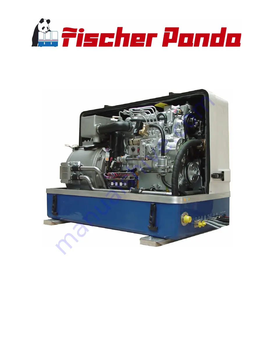
Panda PMS-HD 12-4KU
Super silent technology
230V/400V - 50Hz / 10,5kW
120V/240V - 60Hz / 10,5kW
Fischer Panda GmbH
Manual
Page 1: ...Description of the generator and operation manual Marine Generator Panda PMS HD 12 4KU Super silent technology 230V 400V 50Hz 10 5kW 120V 240V 60Hz 10 5kW Fischer Panda GmbH Manual...
Page 2: ...rer Fischer Panda GmbH 33104 Paderborn reserves all rights regarding text and graphics Details are given to the best of our knowledge No liability is accepted for correctness Technical modifications f...
Page 3: ...ance 35 A 3 9 Components of the oil circuit 37 A 3 10 External components 39 A 4 Operation manual 40 A 4 1 Preliminary remark 40 A 4 2 Daily routine checks before starting 40 A 4 3 Starting Generator...
Page 4: ...Coolant Connection Block at the Generator Capsule 73 C 8 Conservation of the Generator long operation interruption 74 C 8 1 Measures for preparation of winter storage 74 C 8 2 Initiation during Spring...
Page 5: ...ith VCS and ASB 101 D 8 4 VCS Voltage Control 102 D 8 5 Jump Start at High Starting Current Booster 103 D 9 Insulation Test 103 E Tables 105 E 1 Troubleshooting 105 E 2 Types of coil 115 E 3 Inspectio...
Page 6: ...Page 6 Panda_12 4KU_HD PMS_eng R02 Table of contents 8 7 08 Table of contents A 7 1 Terminal connections 142 A 7 2 Configuration and adjustment 143 B Measurements 147 B 1 Hole pattern 147...
Page 7: ...ible turn off the electrical power If you cannot turn off the electrical power pull push or lift the person to safety using a wooden pole rope or some nonconductive material After the injured person i...
Page 8: ...d lift chin Shout Are you OK Look listen and feel for breathing for 3 to 5 seconds 6 Give 2 Full Breaths Keep head tilted back Pinch nose shut Seal your lips tight around victim s mouth Give 2 full br...
Page 9: ...his superiority in efficiency also ensures a fuel saving to the same extent The 100 water cooled Panda generators are currently manufactured in the performance range from 2 to 100 kW in various versio...
Page 10: ...in severe perso nal injury or loss of life This danger symbol refers to electric danger and draws attention to special warnings instructions or procedures which if not strictly observed may result in...
Page 11: ...which tool must be used at maintenance or installation Spanners X required size Hook wrench for oil filter Screw driver for slotted head screws and for recessed head screws Multimeter multimeter with...
Page 12: ...l it has been ascertained that the system into which the generator is to be integrated also corresponds to the machine guideline regulation 98 37 EG This includes the exhaust system cooling system and...
Page 13: ...pective regional authority must be adhered to Only an electrician may carry out installation of the elec trical connections for safety reasons Ground Wire The generator is earthed as series centre and...
Page 14: ...the cable used be UL 1426 BC 5W2 compliant with Type 3 stranding ABYC Section E 11 Cable Size The cable size must be selected taking into account the amperage voltage and conductor length from the pos...
Page 15: ...The Panda Generator A The Panda Generator A 1 Type plate at the Generator Fig A 1 1 Type plate Fig A 1 2 Discription type plate...
Page 16: ...r pump 05 Oil pressure switch 06 Oil filter 07 Sound cover base part 08 Hose for raw water flow for injector nozzle 09 Exhaust outlet 10 Oil dipstick 11 Cooling water filler neck with cap 12 Water coo...
Page 17: ...thermostat housing 07 Thermo switch at thermostat housing 08 Ventilation screw water pump 09 Failure bypass switch 10 Actuator 11 Cooling water connection block 12 Sound cover base part 13 Cooling wa...
Page 18: ...nection 09 Electrical cable fuel pump 2x1 5mm 10 Electrical cable remote control panel 11 Oil drain hose 12 Electrical cable VCS 13 Electrical cable for AC Control box 14 Electrical cable for load 15...
Page 19: ...rnal cooling water expansion tank 03 Backflow to the external cooling water expansion tank 04 Connection external ventilation vlave 05 Sound cover base part 06 Thermo switch at oil cooled bearing 07 C...
Page 20: ...with air filter 04 Thermo switch at cylinder head 05 Cooling water filler neck with cap 06 Water cooled exhaust elbow 07 Hose for backflow to external cooling water expansion tank 08 Oil filler neck...
Page 21: ...nts of Cooling System Raw water Raw water intake The diagram shows the supply pipes for the generator The connection neck for the raw water connection is shown on the left hand side The cross section...
Page 22: ...of the boat even if it is only for a short period of time A hosepipe on the generator casing has been produced for this Both connecting pieces are bridged by a formed piece of hose Fig A 3 3 3 Connect...
Page 23: ...state Fig A 3 4 1 Cooling water filler neck Ventilation pipe The ventilation pipe at the water cooled exhaust manifold leads to the external expansion tank This pipe only serves as a ventilation pipe...
Page 24: ...ia gram Fig A 3 4 4 Freshwater backflow Heat exchanger Separates the raw water system from the freshwater system Fig A 3 4 5 Heat exchanger Cooling water connection block The cooling water is fed to t...
Page 25: ...ing water intake The intake pipe from the external cooling water expansion tank is connected here Fig A 3 4 8 Internal cooling water pump Ventilation screw cooling water pump The ventilation screw abo...
Page 26: ...ese cooling water necks are only required to fill the motor with cooling water in cases of repair The normal cooling water controls may only be carried out at the external expansion tank Fig A 3 4 11...
Page 27: ...y attached to the inside of the sound insulation cap sule for the marine version is supplied on delivery and loose for other makes In all cases a further pre filter with water separator must be instal...
Page 28: ...fore mostly the solenoid 1 Fuel solenoid valve 2 Ventilation screw solenoid valve 3 Magnetic coil Fig A 3 5 5 Fuel solenoid valve Injection nozzles If the engine does not start after the venti lation...
Page 29: ...olenoid A 3 6 Components of combustion air Air suction openings at the sound cover The sound cover is provided at the back side with drillings through which the com bustion air can influx It must be c...
Page 30: ...chamber intake elbow The figure shows the induction elbow at the combustion engine At the front of this induction elbow you can see the hose con nection between air suction housings and induction elb...
Page 31: ...aust connection Exhaust outlet Connect the exhaust pipe with the water lock Fig A 3 6 7 Exhaust outlet A 3 7 Components of the electrical system Connection starter battery 1 Cable for starter battery...
Page 32: ...panel 3 VCS 4 AC Control box Fig A 3 7 2 Load At the front of the sound cover is also the withdrawal for the cable for the main power Depending upon type of the gene rator are here also the cables fo...
Page 33: ...rnal automatic start For the opera tion of this automatic starting system a separate speed sensor is necessary At some models the speed sensor is standard installed At other models the opening for the...
Page 34: ...apter A2 In these terminal boxe there are the elec trical connection points for the AC genera tor Here is also the bridge for the protective grounding of the generator The cover may only be removed if...
Page 35: ...or stop solenoid Fig A 3 7 11 Terminal block A 3 8 Sensors and switches for operating surveillance Thermo switch at cylinder head The thermo switch at the cylinder head serves the monitoring of the ge...
Page 36: ...switch at the endshield The generator bearing is equipped with an oil thermoswitch which switches the engine off if the oil temperature becomes to high 120 C Fig A 3 8 4 Thermo switch at endshield Th...
Page 37: ...ity of starting the generator if the electri cal control switched off due to an error in the cooling system by overheating Fig A 3 8 7 Failure bypass switch A 3 9 Components of the oil circuit Oil fil...
Page 38: ...Oil dipstick Oil filter The oil filter should be exchanged with an oil change Fig A 3 9 3 Oil filter Oil drain hose The Panda generator is equipped that the engine oil can be drained over an drain ho...
Page 39: ...must be installed Fig A 3 10 1 External fuel pump AC Control box At operating the generator the operating voltage of 120 230 and or 230 400V lies at the AC Control box It must be guaranteed that the g...
Page 40: ...y be regularly charged by a suitable battery charging device i e at least every 2 Months A correctly charged starter battery is necessary for low temperatures A 4 2 Daily routine checks before startin...
Page 41: ...with the temperature switch contacts which automatically switch off the generator in case of faults There is only safety if these systems are regularly checked and these systems will protect the gen e...
Page 42: ...ortant to switch off the generator electrical load before the generator is shut down Before stopping the generator it is highly recommended that electrical devices e g refrigerating compressors air co...
Page 43: ...minal performance of the generator is fore mostly for short term use It is however required to start electric motors with high starting current or achieve special starting procedures at peak loads 70...
Page 44: ...in the 60 Hz version In some countries even substantially larger tension deviations are being called normally The Fischer Panda generators are aligned that they keep these default values during norma...
Page 45: ...r Panda dealer B 3 Setting the Speed Governor of the Actuator The speed of the generator is determined by two independent settings an upper and lower speed governor By means of the adjusting nuts on t...
Page 46: ...ning the spindle of the servomotor until the voltmeter reaches 260 Volts 130 Volts 7 Turn the governor screw firmly against the stop setting of the speed adjustment lever 8 Secure the governing screw...
Page 47: ...lts 110V 7 Tighten both nuts tightly against each other 8 Once again check whether the lower generator voltage of the generator without load is limited to 225 volts 110 volts Setting the upper speed l...
Page 48: ...out when over or under heated All screws on the rotary servomotor and the spindle should be secured with a screw securing solution so that they can be easily loosened The trapezoidal thread spindle m...
Page 49: ...actuator current but an overloading over a longer period of time can still damage the winding of the actuator This will not effect the operation ability of the engine but it can happen that the cranki...
Page 50: ...med that the actuator operates smoothly The electrical groups of components must then be checked 1 Re connect plug 2 Start generator 3 Turn the actuator by hand to check whether the Spindle is reverse...
Page 51: ...ted is too low then the consumers should be disconnected one after the other in order to reduce the load on the generator Generally the problem is then solved The frequency should be checked if the ou...
Page 52: ...ich is fitted with a buzzer The multi meter should be switched to open and both capacitor connections connected to the multi meter Fig B 4 2 1 Multimeter Should a steady sound or no sound be heard the...
Page 53: ...rises from the rest magnetism of the rotor which induces a voltage in the winding B 4 4 Measuring the Ohm Resistance of the Generator Windings If a short circuit could not be found by using a multi me...
Page 54: ...L3 L1 DVS 60 Hz L1 L2 L3 L1 1 2 3 4 The generator must be sent for a check to the factory or be re winded locally when a pass beep should be detemined Windings data can be requested for this if it is...
Page 55: ...not use a battery bank or the generator starter battery this could damage the winding The DC voltage only may be applied for a short time 1 2 seconds In the winding the remaining magnetism is restore...
Page 56: ...failure bypass switch enables an immediate restart facility of the generator should it cut out even if this was caused by over heating There is normally a requirement to wait until the motor has cool...
Page 57: ...ake or a fault with the external cooling system Continual use of the starter failure bypass switch should be avoided while the generator cuts out during operation The generator must always run without...
Page 58: ...Generator Failure Seite 58 Panda PMS 8 000 NE 42 NE Manual R04 Kapitel B Generator Failure 8 7 08 Blank...
Page 59: ...ental influences They wear quickly in an environment of dry air oil and fuel vapours and high temperatures The hoses must be checked regularly for elasticity There are operating situations when hoses...
Page 60: ...fed through the sound insulation capsule Fig C 3 1 Oil Drain Hose Oil Drain Screw The oil can be discharged by opening the oil drain screw For countering use a second wrench Fig C 3 2 Oiil Drain Scre...
Page 61: ...er strap Fig C 3 4 Oil Filter Change Oil filter gasket The gasket should be coated with oil before inserting the new oil filter Tighten the oil filter by hand only Fig C 3 5 Oil Filter Gasket Refill O...
Page 62: ...d the Max marking Fig C 3 7 Oil Dipstick C 3 1 Check Oil Level of the Oil Cooled Bearing The oil level of the oil cooled bearing must be checked regularly C 4 Checking the water separator in the fuel...
Page 63: ...witch and keep firmly pressed The electrical fuel pump must be audible Switching on and off the solenoid valve at the gene rator will be audible by pressing the failure bypass switch if capsule remo v...
Page 64: ...sfully starting The injection line must be raised by several millimetres 6 Switch main switch OFF Fig C 4 1 3 Injection nozzles C 4 2 Exchange of the Fuel Filter Exchanging the filter depending upon f...
Page 65: ...Maintenance Instructions Seite 65 C 4 3 Exchange the Air Filter Mat 1 Open the air suction housing by loosen the six screws on the housing cover Fig C 4 3 1 Air Suction Housing 2 Change the air filter...
Page 66: ...system This ventilating procedure must be repeated several times ATTENTION The generator must be switched off before opening the ventila ting points Pay attention that the external coolant expansion...
Page 67: ...cooling water screws and then start the generator 5 Run the generator for approx 60 Seconds then switch off 6 Refill cooling water via the compensa tion tank Fig C 4 4 Colling Water Filler Cap 7 The c...
Page 68: ...he closed sound insulated capsule about 85 C can be a reason for a reduced lifespan of the v belts It is possible that the softener in the rubber com pound lose their effect after a short operating ti...
Page 69: ...beneath the Alternator 3 Press the alternator in the direction of the thermostat casing 4 Exchange Belt Pulleys Fig C 4 5 3 DC Alternator 5 Re tighten Belt Pulleys The belt pulleys should only be tig...
Page 70: ...p 2 Longer Suction Distance of Cooling Water If the cooling water suction distance is long or is blocked this has a negative effect on the impel ler so that an under pressure occurs in the cooling wat...
Page 71: ...8 000 NE 42 NE Manual R04 Kapitel C Maintenance Instructions Seite 71 C 6 1 Exchanging the Impeller 1 Close the seawater valve Fig C 6 1 1 Seawater valve The seawater pump is located on the front sid...
Page 72: ...means of multi grip pliers 3 Mark the impeller to make sure that it is in the correct position when re instal lation is carried out Fig C 6 1 4 Impeller 4 Check the impeller for damage and replace it...
Page 73: ...is identifiable from the outside of the coolant terminal block then the block must be replaced at regular intervals at least once per year In this case the coolant terminal block is a wearing part It...
Page 74: ...oubly check the hose connections at all seawater valves and if possible protect them with double hose clamps 7 Dismount the cooling water pump impeller and check for wear The impeller may not remain i...
Page 75: ...r to clear blossoming of the material If the surface is only grey coated this is only an indication for the fact that alumi num came into contact with condensed moisture 17 Use of a air dehumidifier T...
Page 76: ...Maintenance Instructions Seite 76 Panda PMS 8 000 NE 42 NE Manual R04 Kapitel C Maintenance Instructions 8 7 08...
Page 77: ...s i e This acts as an amplifier of airborne sounds in the most unreasonable case An improvement can be achieved by reinforcing these surfaces with ribs In addition the breakthroughs which interrupt th...
Page 78: ...t for laying pro tected i e in pipe at a temperature up to a max of 70 C 160 F The on board circuit must also be fitted with all essential fuses ATTENTION Before working installation on the System rea...
Page 79: ...the chapter Service instruction for marine generators corrosion protection D 3 2 Installation of the thru hull fitting in Yachts It is good practice for yachts to use a thru hull fitting with an integ...
Page 80: ...er a period of time Ensure that the genset is installed so that the intake pump can be easily accessed If this is not possible an external intake pump could be installed in an easily accessible locati...
Page 81: ...taken into consi deration if installed at the mid ship line The water hose for the external vent valve is located at the back of the sound insula ted cover This hose is split in the middle and extende...
Page 82: ...the hose for the external vent valve Fig D 1 Connection Vent Valve and bend it upwards Both hose ends must be led out outside of the sound cover to one point if possible 600 mm over the waterline at t...
Page 83: ...oling D 3 7 Indirect Cooling of the Genset Housing by the Heat Exchanger Fig D 3 7 1 Installation Scheme Indirect Cooling of teh Genset Housing 1 Vent valve 2 Coolant connection block 3 Raw water pump...
Page 84: ...such a way that its lower edge is at least 500 mm more highly arranged than the upper edge of the sound cover If this 500 mm should be fallen below i e the cooling water expansion tank is lower insta...
Page 85: ...ed Fig D 4 2 1 Expansion ttank 2 Open vent screw on the pipe socket of the internal cooling water pump Close the vent screw when air free water comes out Check the water level in the expansion tank du...
Page 86: ...ilating process repeated checks must be made to check the cooling water is indeed circulating If there are air bubbles in the internal cooling water pump it could be that the cooling water is not circ...
Page 87: ...e difference exists between cooling water in flow and cooling water return flow by use of the hand Feel the cooling water in flow line at the internal cooling water pump Feel the cooling water return...
Page 88: ...llation Instructions 8 7 08 D 4 6 Scheme for Freshwater Circuit at Two Circuit Cooling System Fig D 2 Scheme for Freshwater Circuit at Two Circuit Cooling System 1 Expansion Tank 2 Exhaust Manifold 3...
Page 89: ...diameter of 30 mm The water lock must be installed at the lowest point of the exhaust system An optional noise insulated water lock can also be installed The exhaust hose descends from the capsule to...
Page 90: ...exhaust water separator the cooling water is derived over a separate pipe The exhaust noises emana ting from the exterior of the yacht are strongly decreased Particularly the water splash The water f...
Page 91: ...the thru hull exhaust outlet has to be mounted far from the generator an exhaust water separa tor must definitely be installed The raw water from the separator must then run along the shortest possib...
Page 92: ...s fuel pump Generally forward and return fuel flow pipes must be mounted to the diesel tanks Do not connect the generator fuel supply lines with any other fuel lines of other diesel systems The follo...
Page 93: ...rical fuel pump 12 V DC The fuel pump must be installed close at the fuel tank The electrical con nections are pre loaded at the generator with the lead planned Fig D 6 2 1 Electrical Fuel Pump Suctio...
Page 94: ...fter the generator has been switched off if it is not possible to use the return flow pipe as a submerge pipe placed in the tank The instructions Bleeding Air from the Fuel System must be read after i...
Page 95: ...3 After the fuel pump has been running 3 to 4 minutes because the failure bypass switch has been pressed down the bleeding screw of the solenoid valve has to be unscrewed The switch has to be continuo...
Page 96: ...en if the other batteries are discharged A further advantage of a separate starter battery is that it isolates the generator s electric system from the rest of the boat s DC system i e minus pole is n...
Page 97: ...sks also see the DC circuit diagram 1 Starter motor relay 2 Pre glow relay glow plugs 3 Fuel pump relay Fig D 7 1 3 DC Relay All Panda generators are equipped with an independent 12 V DC starter motor...
Page 98: ...re that all electrical installations including all safety systems comply with all required regulations of the regio nal authorities This includes lightening conductor personal protection switch etc D...
Page 99: ...nd the ship s electrical supply system This switch must used to ensure that all AC consumers can be switched off at once This switch should also be installed to keep the generator and shore grid power...
Page 100: ...in the AC Control box must be disconnected Once such a ground protection cable is installed it must be connected to the ground straps of all on board electrical devices In order to monitor the electr...
Page 101: ...be connected by electrical wires high voltage and low voltage to the generator The front panel must always be closed since the AC Control box produces 400 V during opera tion The AC Control box must b...
Page 102: ...d is reached The speed gauge is governed by an adjusting screw above and below Adjustment of this screw may not occur without the expressive approval of the manufacturer All signals pass through the c...
Page 103: ...ground connection then ALL electrical devices must also be connected to this common ground usually ground contacts are attached to the devices metallic housings The electrical system installation mus...
Page 104: ...Installation Instructions Seite 104 Panda PMS 8 000 NE 42 NE Manual R04 Capture D Installation Instructions 8 7 08 Blank...
Page 105: ...replace if necessary Measurering voltage on the VCS circuit board is mis sing Check VCS System check cable connections GENERATOR VOLTAGE FLUCTUATES Cause Solution 1 Disturbances on the electrical sys...
Page 106: ...gram Relay K2 Fuse Fuel pump not working Check fuel filter and pump clean if necessary Lack of fuel Check fuel supply Glow plugs not working correctly Check glow plugs and heating time Too much air in...
Page 107: ...ulty MOTOR SPEED DROPS Cause Solution Lack of fuel Check fuel supply system fuel filter renew if necessary check fuel pump check fuel lines bleed if necessary Lack of intake air Check air intake paths...
Page 108: ...use Solution Generator is overloaded Check electrical load and switch off unnecessary load Insufficient intake air Check intake air filter clean if necessary Fuel injector faulty Replace injector Valv...
Page 109: ...ca 0 1 ca 0 1 ca 0 08 ca 0 9 ca 0 8 ca 0 3 ca 0 4 ca 0 4 ca 0 2 Table 1 Resistor generator coil HP1 L N Ohm L Z Ohm Mains 120V 60Hz Panda 8000 Panda 9000 Panda 12000 Panda 18 Panda 24 ca 0 7 ca 0 65 c...
Page 110: ...a 3 5 ca 2 3 ca 1 8 ca 1 3 ca 0 9 ca 2 3 ca 2 3 ca 2 3 ca 1 5 ca 1 1 ca 0 8 ca 0 6 Table 5 Voltage values stator coil Terminal Panda 8000 Panda 9000 Panda 12000 Panda 14000 Panda 18 Panda 24 Panda 30...
Page 111: ...NE 20 20 40 8 8 Panda PMS 14000 NE 20 20 40 8 8 Panda PMS 18 NE 25 20 50 8 8 Panda PMS 24 NE 25 20 50 8 8 Panda PMS 30 NE 25 20 50 8 8 Panda PMS 33 KU 30 25 50 8 8 Panda PMS 42 KU 30 30 50 8 8 Panda P...
Page 112: ...4 120 V 60 Hz 89 1 A 30 1 A 161 1 A Panda 12000 230 V 50 Hz Panda 12000 400 V 50 Hz Panda 12000 120 V 60 Hz 41 7 A 13 7 A 89 0 A Panda 30 230 V 50 Hz Panda 30 400 V 50 Hz Panda 30 120 V 60 Hz Anfrage...
Page 113: ...rpm 3000rpm 3000rpm 3000rpm Idle running speed a a progressive speed by VCS 3120rpm 2900rpm 3120rpm 2900rpm 2900rpm 2900rpm 2900rpm 2900rpm Valve clearance engine cold 0 2mm 0 2mm 0 2mm 0 2mm 0 2mm 0...
Page 114: ...0UpM 3000UpM 3000UpM Idle running speed a 2900UpM 2900UpM 2900UpM 2900UpM 2900UpM 2900UpM 2900UpM 2900UpM Valve clearance engine cold 0 2mm 0 2mm 0 2mm 0 2mm 0 2mm 0 2mm 0 2mm 0 2mm Cylinder head nut...
Page 115: ...Tables Panda PMS 8 000 NE 42 NE Manual Chapter E Tables Page 115 E 2 Types of coil HP1 230V 50 Hz HP1 120V 60 Hz HP3 400V 50 Hz...
Page 116: ...Tables Page 116 Panda PMS 8 000 NE 42 NE Manual Chapter E Tables HP3 120V 60 Hz DVS 400V 50 Hz DVS 120V 240V 60 Hz...
Page 117: ...8 1 1 1 1 1 1 1 unit s base mount screws 19 6 6 6 6 6 6 6 check electrical cables 20 1 1 1 1 1 1 1 motor reinforced mountings 21 1 1 1 1 1 1 1 starter motor mounting screws 22 1 1 1 1 1 1 1 screws gen...
Page 118: ...er the second number refers to the fluidity with heat Complete yearly oils have usually SAE 10W 40 SAE 15W 40 etc Quality of oil The quality of an engine oil is specified by the API standard American...
Page 119: ...OTECT PLUS G 48 Engine coolant automotive industry Product description Product name GLYSANTIN PROTECT PLUS G48 Chemical nature Monoethylenglycol with inhibitors Physical form Liquid Chemical and physi...
Page 120: ...Tables Page 120 Panda PMS 8 000 NE 42 NE Manual Chapter E Tables...
Page 121: ...Valve clearance engine cold 0 145 0 185 mm Cylinder head nut torque 63 7 68 6 Nm Compression ratio 23 1 Lubrication oil capacity 6 0 l Fuel consumption b b 0 35l kW electrical power the randomized val...
Page 122: ...Generator Data F 2 Capsule measurements...
Page 123: ...P6 RE0703_Kunde_eng R02 8 7 08 Generator Control Panel P6 Manual 12V version 21 02 02 009H 24V special version 21 02 02 012H Option automatic adapter 21 02 02 016H Option master slave adapter 21 02 02...
Page 124: ...Actual Panel Generator Control P6 RE0703_Kunde_eng R02_8 7 08 Replace Panel Generator Control P6 RE0703_Kunde_eng R01_28 11 07 Revision Page Upgrade the whole manual ATTENTION Please read the safety i...
Page 125: ...07 08 09 10 01 LED for coolant temperature red1 02 LED for waterleak red yellow1 sensor optional 03 LED for AC voltage fault red yellow1 04 LED for AC voltage ok green1 05 LED for winding temperature...
Page 126: ...8 7 08 A 2 Rear view 12V version Fischer Panda Art No 21 02 02 009H Fig A 2 1 Panel rear view 12V version 02 01 03 04 01 Control board 02 Terminal block master slave adapter left row automatic adapter...
Page 127: ...sion Fischer Panda Art No 21 02 02 012H Fig A 3 1 Panel rear view 24V version 02 01 04 05 06 03 01 Control board 02 Terminal block master slave adapter left row automatic adapter right row 03 Fuse 630...
Page 128: ...pump switched on must be adjusted by solder Jumper This function is available only in 12V operation 7 AC Control IN AC control display Input for NC open collector sensor switch to GND N OK The input l...
Page 129: ...Engine input for contact which closes in case of error 2 J202 1 2 Water leak input Replace air filter for contact which opens in case of error 2 2 3 Water leak input Replace air filter for contact wh...
Page 130: ...68R is switched on with Panel ON 1 open X Dynamo excitation resistor is deactivated J101 closed X 12V operation open 24V operation not possible J201 1 2 X T Engine input for contact which opens in cas...
Page 131: ...not equipped Jumper Status Conf Description J1 closed during operation of the start button heat is along operated open X Function deactivated J3 1 2 Dynamo excitation resistor 68R is switched on with...
Page 132: ...ND Configuration and setting sheet KE03 Standard jumpering for generators with alternator Panel only for 12V operation The safety device is installed with the value 0 63AT The circuit parts for 24V op...
Page 133: ...jumper with soldering surface no 1 Equivalent resistance for load control lamp e g for use with three phase alternator also integrated automatic controller of Bosch The resistance value is 68 3W i e o...
Page 134: ...eak has red LED and switches off 2 3 Input Water leak has yellow LED and does not switch off J207 1 2 X Input AC Fault has red LED and switches off 2 3 Input AC Fault has yellow LED and does not switc...
Page 135: ...ximum in a cold state It is very important that a large expansion area remains above the cooling water level 3 Check if sea cock for cooling water intake is open For safety reasons the sea cock must b...
Page 136: ...of the maximum in a cold state It is very important that a large expansion area remains above the cooling water level 3 Visual inspection Control fixing bolts check hose connectors for leakages contro...
Page 137: ...e range Parallel connection of several loads should be avoided especially if there are loads with electric motors such as air conditioning units in the system In this case the load must be connected S...
Page 138: ...he output Fuel pump clamp 9 generator control panel is switched off The time for the automatic stop procedure can be terminated only by switching off generator control panel prematurely The times for...
Page 139: ...s must not be set Data Parameter Information Operation voltage The automatic adapter power is supplied via the generator control panel P6 The same absolute maximum ratings obtain as with the generator...
Page 140: ...V regulated 9 GND O Current supply ground 11 GND O Current supply ground 13 Heat signal I Heat is active if the input is switched to GND 15 Start signal I Start is active if the input is switched to G...
Page 141: ...Panda Art No 21 02 02 015H 12V version Fig A 7 1 Panel 21 02 02 009H with master slave adapter 21 02 02 015H Fischer Panda Art No 21 02 02 01H 24V version Fig A 7 2 Panel 21 02 02 012H with master sl...
Page 142: ...ng the generator off The output voltage corresponds to the operating voltage of the Generator Control Panel P6 less 0 7V 1 4V Each output has a free wheeling diode which short circuits externals volta...
Page 143: ...panel ON OFF switched voltage of clamp X2 1 VBF Consider notes 1 4 36 Error O Output is switched on if a ceitical error is present Consider notes 1 4 Fig A 7 1 2 Terminal connections terminal X3 Notes...
Page 144: ...in case of error 2 J205 1 2 T Winding input for contact which opens in case of error 2 2 3 XM T Winding input for contact which closes in case of error 2 J206 1 2 M Input Water leak has red LED and sw...
Page 145: ...r 2 J202 1 2 Water leak input Replace air filter for contact which opens in case of error 2 2 3 XM Water leak input Replace air filter for contact which closes in case of error 2 J203 1 2 Oil Press in...
Page 146: ...r with soldering surface no X Jumper must be so set XM Jumper function must be so set on the master panel is selected M Jumper must be set exactly the same as on the master panel 1 Equivalent resistan...
Page 147: ...icht Ersatz f r Ersetzt durch Blatt Panel Generator Control 06 03 2007 jschaefers 1 A3 Otto Hahn Str 32 34 D 33104 Paderborn Tel 05254 9202 0 Fax 05254 85724 info fischerpanda de www fischerpanda de A...
Page 148: ...Measurements Page 148 Panel Generator Control P6 RE0703_Kunde_eng R02 Chapter B Measurements 8 7 08 Intentionally Blank...