Festo CMMP-AS-***-M3 Series Description Download Page 80

8

Service functions and diagnostic messages

80

Festo – GDCP-CMMP-M3-FW-EN – 1203NH

8.2.3

Acknowledgement of error messages

Error messages can be acknowledged through:

the parametrisation interface

the fieldbus (control word)

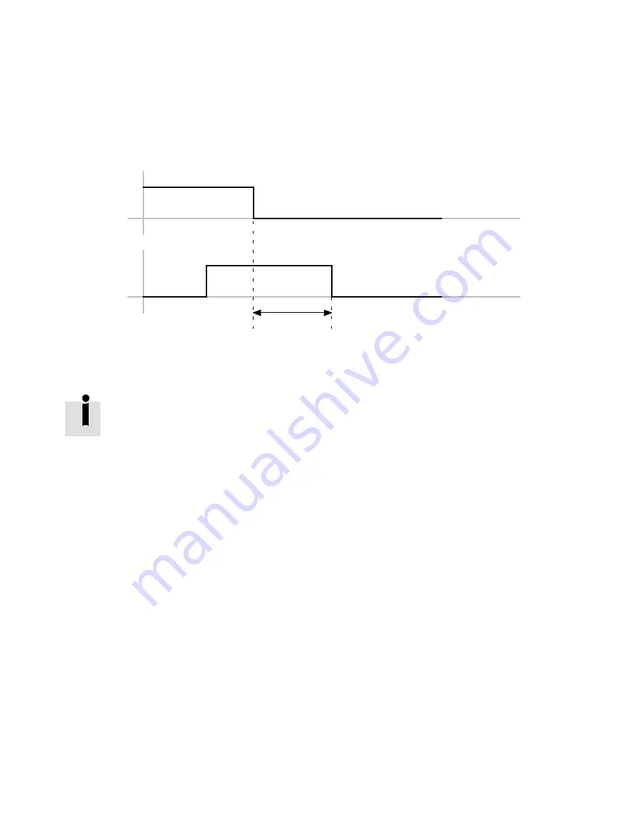
a decreasing edge at DIN5 [X1]

Controller

enable

DIN5 [X1]

1

“Error active”

1 L

80 ms

Fig. 8.1

Timing diagram: acknowledge error

Diagnostic events which are parametrised as warnings are automatically acknowledged

when the cause is no longer on hand.

8.2.4

Diagnostic messages

The significance and their measures for diagnostic messages are summarised in the following chapter:

(

chapter A Diagnostic messages).

Summary of Contents for CMMP-AS-***-M3 Series

Page 1: ...Description Functional description firmware for motor controller CMMP AS M3 FW 4 0 1501 1 0 760330 1203NH Motor controller CMMP AS M3 ...

Page 2: ...ntification of hazards and instructions on how to prevent them Warning Hazards that can cause death or serious injuries Caution Hazards that can cause minor injuries or serious material damage Other symbols Note Material damage or loss of function Recommendations tips references to other documentation Essential or useful accessories Information on environmentally sound usage Text designations Acti...

Page 3: ...alists requirements for the personnel 10 1 2 3 Range of application and certifications 10 2 Operating modes and functions 11 2 1 Overview 11 3 Control interfaces 12 3 1 Control interfaces 12 3 1 1 Overview of interfaces 12 4 Fieldbus options 13 4 1 Supported fieldbuses 13 4 2 Required I O connection for fieldbus control 14 5 Service 15 5 1 Supported functions 15 5 2 Memory card 15 5 2 1 Load firmw...

Page 4: ... Homing via I O 37 6 2 6 Timing diagrams 38 6 3 Jog mode 40 6 3 1 Function 40 6 3 2 Process 41 6 3 3 Jog mode parameters 42 6 4 Teach in function 44 6 5 Setpoint specification 45 6 5 1 Analogue setpoint 45 6 5 2 Digital nominal value 47 6 5 3 Master slave 51 6 5 4 Flying saw 51 6 5 5 Scope of functions for cam discs CAM 53 6 6 Second measuring system 53 6 6 1 Technology 53 6 6 2 Example toothed be...

Page 5: ...current speed and position controller 75 8 Service functions and diagnostic messages 76 8 1 Protective and service functions 76 8 1 1 Overview 76 8 1 2 Phases and mains failure detection with 3 phase motor controllers 76 8 1 3 Overload current and short circuit monitoring 76 8 1 4 Overvoltage monitoring for the intermediate circuit 77 8 1 5 Temperature monitoring for the heat sink 77 8 1 6 Monitor...

Page 6: ...MMP AS M3 HW see Tab 1 Target group This description is intended exclusively for technicians trained in control and automation technology who have experience in installation commissioning programming and diagnosing of positioning sys tems Service Please consult your regional Festo contact if you have any technical problems Product identification versions This description refers to the following ve...

Page 7: ...ntrol and parameterisation of the motor controller through the Festo profile FHPP with the following fieldbuses CANopen PROFIBUS DeviceNet EtherCAT PROFINET Ethernet IP Description CiA 402 DS 402 GDCP CMMP M3 C CO Control and parametrisation of the motor controller through the device profile CiA 402 DS402 with the following fieldbuses CANopen and EtherCAT Description CAM Editor P BE CMMP CAM SW Ca...

Page 8: ...intenance repair and cleaning work and when there have been long service interruptions 1 Switch off power to the electrical equipment via the mains switch and secure it against being switched on again 2 After switch off wait at least 5 minutes discharge time and check that power is turned off before accessing the controller The safety functions do not protect against electric shock but only agains...

Page 9: ... of PELV circuits protection from electric shock protection from direct and indirect contact in accordance with IEC DIN EN 60204 1 is ensured Electrical equipment of machines General requirements 1 1 3 Designated use The motor controller CMMP AS M3 is intended for installation in machines or automated systems and is to be used as follows in a faultless technical condition in original status withou...

Page 10: ... in the technical data of the motor controller appendix A of the documentation GDCP CMMP AS M3 HW and of all con nected components Only compliance with the limit values or load limits permits operation of the product in accordance with the relevant safety regulations Observe the instructions and warnings in this documentation 1 2 2 Qualification of the specialists requirements for the personnel Th...

Page 11: ...rating mode for executing a positioning record direct mode with force torque control current control This operating mode permits spe cification to the controller of an external force torque setpoint value relat ive to the motor current All specifications on forces torques refer to the motor nominal torque or the motor nominal current Since force torque are proportional to the motor current only th...

Page 12: ...HPP DeviceNet FHPP EtherCAT FHPP CiA 402 EtherNet IP FHPP PROFINET FHPP Tab 3 1 Control interfaces 3 1 1 Overview of interfaces Control interface Function Operation Mode Reference Analogue Analogue setpoint spe cification Speed adjustment Torque regulation Chap 6 5 1 45 ff Synchronisation Flying saw Synchronisation slave Cam disc Chap 6 5 2 47 ff I O Record selection Jog mode Linked position sets ...

Page 13: ...ith the CiA DS 301 and the drive profile in accordance with the CiA 402 have been implemented Independent of the field bus a factor group can be used so that application data can be transferred into user specific units Fieldbus Connection Interface type Documentation type CANopen X4 GDCP CMMP M3 C CO CiA 402 GDCP CMMP M3 C HP FHPP DeviceNet Ext1 CAMC DN GDCP CMMP M3 C HP FHPP DriveBus X4 GDCP CMMP...

Page 14: ... V DC Controller enable DIN5 Output stage enable DIN4 Limit switch0 DIN61 Limit switch1 DIN71 Operating status DOUT0 Default motion complete DOUT1 The connection plan shows the switch position in the active operating state 1 The limit switches are set by default to N C contact configuration over FCT Fig 4 1 Connection diagram required I O interface ...

Page 15: ...om the memory card to the CMMP AS M3 Supported card types MMC1 version 3 SD1 version 1 and 2 SDHC1 from class 2 Supported file systems FAT16 FAT32 Format filename 8 3 1 Recommended are industry suitable cards from the Festo accessories programme Tab 5 2 Characteristics of the memory card Note The filenames may only consist of upper case letters If lower case letters are used when the filename is i...

Page 16: ... these points is applicable the firmware update is cancelled and an error reported The decimal point in the digit representation with 7 segments is also displayed in case of errors that were detected or triggered through the bootloader If no memory card was found or there is no parameter set on the memory card the para meter set valid before the firmware download is loaded If no memory card was fo...

Page 17: ...the digit representation with 7 segments 9 The motor controller automatically starts the firmware by triggering a RESET A firmware download is also possible if the firmware programming has been cancelled and the controller does not have valid firmware But observe that the controller in this case may have a different IP address if it procures it through DHCP Errors may occur in firmware download Po...

Page 18: ...alid value Error during parameter access read or write 5 3 3 Save parameter set via Ethernet A parameter set can be stored via the Ethernet interface X18 For computers that use Windows Vista or Windows 7 as operating system the TFTP client and ports must be specially activated or opened for the firewall Procedure with the program TFTP EXE 1 Make sure that the output stage enable is switched off 2 ...

Page 19: ... often as desired in a given direction After the positioning range is reached the actual position runs over it without triggering an error This overrunning must be taken into account by the controller The positioning controller is parameterised via a target table This contains entries for parameterising a target via a communication interface and also target positions that can be access via the dig...

Page 20: ... modulo axis The target position of the positioning record is not travelled to with modulo correction Example 490 the axis travels positively around 490 Positioning with analogue setpoint The target position is determined through the analogue setpoint specification at AIN0 X1 The follow ing options are available Absolute reference to the project zero point Relative reference to the last target pos...

Page 21: ...e The direction of movement of the axis is always positive Negative The direction of movement of the axis is always negative Auto The direction of travel is determined automatically from the current position target position and additional options absolute relative relative related to last target etc Command record continuation Record continuation consists of a defined sequence of positioning recor...

Page 22: ...ade This decision is made by the first detected edge after the current positioning motion is completed Additional parameters Ign Stop Ignore STOP input The signal of the digital input is ignored for this positioning record End speed Specifies the end speed of the positioning record Default 0 rest when the setpoint position is reached The current positioning record is ended at the target position w...

Page 23: ...nchronisation is deactivated when positioning is started if it was not already Positioning starts with the values for speed and acceleration entered in the posi tioning record Tab 6 2 Commands for synchronisation Remaining Distance Enter the amount for the remaining distance message TFF torque feed forward This value is used to permit the motor greater dynamic response during acceleration when lar...

Page 24: ...he START signal the number of the selected positioning record is taken over and the drive carries out the record 6 1 4 Stop of the record selection through digital halt The digital halt stops in positioning mode with the parameterised ramp of the positioning record After that the drive is controlled brake is opened 6 1 5 Record selection with record continuation Function Record continuation consis...

Page 25: ...ng run When the START signal is reset 1 0 confirmation follows via the ACK signal 0 1 After completion of the positioning job the MC signal is set again 0 1 HOME NEXT1 2 Subsequent positions of a positioning record for record continuation through posi tioning record number and digital inputs Execution travel to the subsequent position corresponds to the logic operation of the digital inputs NEXT1 ...

Page 26: ...long as position 4 has not been reached yet edge changes at DIN0 and DIN1 are recorded positioning is not interrupted During the ongoing positioning first a sig nal edge appears at DIN0 0 1 after that an edge at DIN1 0 1 After target posi tion 4 is reached positioning is started to Pos 20 If position 4 is reached before an edge occurs a rising edge at input NEXT1 DIN0 0 1 causes approach of the ta...

Page 27: ...of rotation from positioning record The direction of rotation is not universally defined but can be indi vidually defined for each positioning record The following settings are possible in the positioning record positive The direction of movement of the axis is always posit ive Absolute and relative positioning negative The direction of movement of the axis is always negat ive Absolute and relativ...

Page 28: ...lute positioning homing must be executed and the dimensional reference sys tem defined at initial commissioning If the drive does not use a multi turn absolute en coder homing must be repeated at each switch on or reset To be able to travel to an absolute unique position in the positioning range the drive must be refer enced to a measuring reference system Homing of the drive comprises Homing Esta...

Page 29: ...ove dir ectly to the axis zero point if it has been entered in the parameters The drive homes against a stop a limit switch or a reference switch The motor current increases when the drive reaches a stop Since the drive must not continuously home against the stop it must move at least one millimetre back into the stroke range Procedure 1 Search for the homing point corresponding to the configured ...

Page 30: ...rst index pulse This position is taken as the homing point 3 If this is parameterised travel at positioning speed to the axis zero point Index pulse Positive limit switch 07h 7 Reference switch in positive direction with index pulse1 1 If reference switch inactive Travel at search speed in positive direction to the reference switch If the stop or limit switch is approached Travel at search speed i...

Page 31: ...d in negative direction to the negative limit switch 2 Travel at creep speed in positive direction until the limit switch becomes inactive This posi tion is taken as the homing point 3 If this is parameterised travel at positioning speed to the axis zero point Negative limit switch 12h 18 Positive limit switch 1 If positive limit switch inactive Run at search speed in positive direction to the pos...

Page 32: ...direction to the reference switch If the stop or limit switch is approached Travel at search speed in positive direction to the reference switch 2 Travel at creep speed in positive direction until the homing switch becomes inactive This pos ition is taken as the homing point 3 If this is parameterised travel at positioning speed to the axis zero point Homing Switch 21h 33 Index pulse in negative d...

Page 33: ...p speed in positive direction until the next index pulse This position is taken as the homing point 3 If this is parameterised travel at positioning speed to the axis zero point Index pulse FEh 2 Positive stop with index pulse1 2 1 Travel at search speed in positive direction to the stop 2 Travel at creep speed in negative direction un til the next index pulse This position is taken as the homing ...

Page 34: ... point 4 If the axis zero point 0 Travel at positioning speed to the axis zero point Homing Switch E5h 27 Reference switch in negative direction with travel to stop or limit switch 1 Run at search speed in negative direction to stop or limit switch 2 Travel at search speed in positive direction to the reference switch 3 Run at crawl speed in positive direction until reference switch becomes active...

Page 35: ...on of the commutation position This option must be marked to suppress this No synchronisation during homing Suppresses switching off of the synchronised position during hom ing X10 No encoder emulation during Homing During homing no encoder signals are output at X11 Reference switch at index pulse of X2B Evaluation of a reference pulse of the shaft encoder at X2B for determination of the reference...

Page 36: ...ft Single turn encoders that are set to permanently homed are already permanently homed on delivery The absolute zero point is stored by the manufacturer in the EEPROM of the encoder Note Incorrect positioning of the axis Drives with absolute value encoders are always homed at switch on to the absolute encoder zero point stored in the encoder For comparison between the homing point of the current ...

Page 37: ...ally required after each switch on You can permanently home the drive for specific applications e g for modulo positioning 0 1 R so that the status referenced is automatically set at switch on Homing at switch on can then be option ally eliminated as with the multi turn encoder 6 2 5 Homing via I O Homing via I O can be started through the following methods A requirement in both cases is an active...

Page 38: ... Timing diagrams Start DIN 2 1 HA MC Speed 0 E0 E1 3 4 5 HA HOMING_ACTIVE MC MOTION COMPLETE E0 Limit switch 0 E1 Limit switch 1 1 0 10 ms 2 20 ms 3 Dependent on braking ramp 4 Dependent on braking ramp 5 20 ms Fig 6 2 Timing diagram homing without error ...

Page 39: ...EN 1203NH 39 Start DIN 2 1 HA MC Speed 0 ERR 3 4 5 Error HA HOMING_ACTIVE MC MOTION COMPLETE ERR Error 1 0 10 ms 2 20 ms 3 Dependent on braking ramp 4 50 ms x x delay until brake locked 5 0 10 ms Fig 6 3 Timing diagram homing with error ...

Page 40: ... 3 Jog mode 6 3 1 Function In the Operation enabled status the drive can be travelled through jogging in a positive or negative direction This function is usually used for Moving to teach positions Drive free running e g after a system malfunction Manual travel as a normal operating mode manually operated feed The jog mode can be controlled as follows Fieldbus FHPP jog mode I O interface through t...

Page 41: ...th the pre set maximum deceleration To protect the mechanics smoothing can also be parameterised All parameters can be set separately for positive and negative travel direction If the drive is referenced The drive stops automatically if it reaches a software end position The software end position is not over travelled the path for stopping is taken into account according to the ramp set The jog mo...

Page 42: ...n of crawling until the shift to maximum speed Tab 6 10 5 Max speed Maximum speed during jog mode Acceleration takes place with the ramp defined under Acceleration and Smoothing Tab 6 10 2 Acceleration Setpoint for acceleration of the drive during jog movements Tab 6 10 3 Deceleration Setpoint for deceleration of the drive during jog movements Tab 6 10 4 Smoothing Smoothing in acceleration value i...

Page 43: ...6 Functions Festo GDCP CMMP M3 FW EN 1203NH 43 Negative 2 1 Positive MC Speed 0 1 2 Speed 0 MC MOTION COMPLETE 1 0 10 ms 2 Dependent on braking ramp Fig 6 5 Timing diagram Jog positive negative ...

Page 44: ...arily saved position data a positive edge at the parameterised Save position input is required The parameterised output Saving process is running goes to High at the start of the saving process Completion of the saving process is signaled through a Low signal at the Saving pro cess is running output Data are temporarily stored in the volatile main memory of the controller and are immedi ately effe...

Page 45: ...ta via a corres pondingly scaled input signal The setting of the function is dependent on the number of inputs used the selected control interface and the selected operating mode function Setpoint value AIN0 AIN1 AIN2 Torque force x x x Speed x x x Position x Tab 6 12 Setpoint value via analogue inputs Scaling Specify in the FCT which value of the respective input variables corresponds to an input...

Page 46: ... voltage up to which the setpoint value 0 is set to achieve a defined rest of the drive for example in the speed control mode independently of offset fluctuations noise etc Enter the threshold value U0 0 V an If the input voltage UIN is in the range U0 U0 the set point value 0 is output The offset set for zero balancing is taken into consideration Note that specifying the threshold value means tha...

Page 47: ...ntroller receives the signals of a transmitter e g a second con troller of type CMMx as synchronous setpoint value The interpretation of the setpoint value corresponds to the setting of the operating mode of the CMMP AS M3 The switch takes place automatically in positioning mode and through setpoint value selector in the speed controlled mode and force torque mode Deactivate Through a configured i...

Page 48: ...ode the signal of the encoder interface X10 is automatically added to the setpoint value Position synchronous without setpoint value addition The synchronous value is taken over directly from the input X10 as setpoint value Setpoint value input through record selection direct mode or analogue input is blocked No setpoint value addition takes place Instructions on further position synchronous appli...

Page 49: ...ector A You can optionally activate a torque limitation via select or B Synchronous speed limiting in torque controlled operation Torque controlled operation with speed limitation via the encoder interface X10 The speed is trans ferred to the slave by the master via the encoder interface X10 and activated as speed limitation via setpoint selector B Required parameters Parameter Description Electro...

Page 50: ...count is dependent on the track signals A B N A B quadrature evaluation The line count of the master is entered with reference to one revolution Index track If the index track is used the specified line count must correspond to the number of lines between index pulses CLK DIR pulse direction The number of increments for the master referred to 90 must be entered here due to the controller s four fo...

Page 51: ...gnal line should be quiet Counting signals switch off The signals CLK CCW are ignored encoders standing still 1 In accordance with RS 422 specification specifications must be taken from the data sheet of the encoder Tab 6 15 Track signals slave input X10 6 5 3 Master slave The motor controller CMMP AS M3 permits a master slave mode which hereafter is designated synchronisation The motor controller...

Page 52: ...is started if it was not already If the master is not sta tionary when positioning starts the offset that occurs will be made up in a controlled manner The posi tioning speed used for this corresponds to the speed of the master plus the positioning speed entered in the positioning record as an excessive increase in speed The entries of the started positioning re cord are likewise used for the acce...

Page 53: ...easurement integrated into the motor is not sufficient There are 2 main reasons for this double safety for instance at safely reduced speed Inclusion of a displacement encoder for secure applications is not described further here The accuracy is not sufficient For instance if the resolution of the motor encoder is not sufficiently large But more frequently it is the mechanics between the motor and...

Page 54: ...le axis Component Type Motor EMMS AS 70 M Rx Axis EGC 80 2000 BS10 KF 0H Mx GK S Feed constant 10 mm R Tab 6 18 Spindle axis components Parameterisation Repetition accuracy Approx absolute accuracy Standard parameterisation mm 0 02 0 05 External displacement encoder mm 0 02 0 05 Tab 6 19 Repetition accuracy of spindle axis 6 6 4 Function in the controller In the controller the position actual valu...

Page 55: ...e 6 6 6 2nd measuring system at the incremental encoder input X10 The incremental encoder input X10 can be used both for motors with encoder and for motors with resolver After switch on 24V voltage off or reset homing must be executed first The interface X10 supports all commonly available incremental encoders with 5 volt level The A B tracks are thereby evaluated fourfold through edge detection 2...

Page 56: ...ition of the motor deviates by x from the actual position of the external displacement encoder In particular for toothed belt axes the value must not be selected too small since an offset always occurs due to expansion of the toothed belt under load In the case of rotative incremental encoders it is not the signal period but the line count per revolution of the external encoder that is specified I...

Page 57: ... is calculated from the encoder in the motor Both values change as a result of shifting by hand The direction of the system can be selec ted freely and is usually simply selected corresponding to the application After selection of a suitable zero point shift the axis by hand in a positive direction If the actual position becomes smaller rather than larger the direction of the 2nd measuring system ...

Page 58: ...he factor 4 Offset Angle Additive correction value in the range from 180 to 180 for electronic adjustment of the zero position Options Disable track A B The incremental signals are not output encoders standing still Suppress zero pulse The emulated incremental encoder does not output a zero pulse Inverse rotation polarity The phase position of tracks A and B is rotated by 180 right rotation field ...

Page 59: ... required time delays brake delay time in particular for holding brakes with high mechanical inertia With longer time delays between command records the automatic function of the holding brake closes the brake and switches off the controller output stage less temperature rise Note In certain applications e g in synchronous mode the automatic function can damage the brake and or the system In the c...

Page 60: ...ive moves only after the switch on delay has expired 1 0 1 0 Drive is moving Automatic 1 0 1 0 Switch off delay MC 1 0 1 0 Switch on delay START 1 0 Controller energised Record completed 1 0 Open brake Start of new positioning record Fig 6 10 Pulse time diagram holding brake with automatic function ...

Page 61: ... expired Activation time of the automatic brake Time in ms between the completion of a positioning motion Motion complete and the resetting of the brake output providing in this period of time there is no new START signal The switch off delay follows after the activation time Value 0 deactivates the automatic brake Tab 6 23 Parameter safe brake control 6 7 3 Position trigger The position triggers ...

Page 62: ...r DIN9 can be selected With every rising and falling edge at the configured sample input the current position value is written into a register of the controller and can afterwards be read out through the higher order controller PLC IPC Additional information on the available parameters can be found in the documentation for FHPP GDCP CMMP M3 C HP or CANopen GDCP CMMP M3 C CO 6 7 5 Software limit sw...

Page 63: ... drive since synchron isation remains active Synchronisation must be explicitly terminated by starting a new positioning record without synchronisation or by using the digital input Disable sync 6 7 7 I O X1 Standard assignment and extension of the digital I Os The motor controller CMMP AS M3 has standard 10 digital inputs DIN0 DIN9 and 4 digital out puts DOUT0 3 The existing digital inputs DIN0 9...

Page 64: ...1 DOUT3 Configurable DIN12 AIN1 Configurable trigger level at 8 V DIN13 AIN2 Configurable trigger level at 8 V Tab 6 26 Assignment DIN DOUT Activated signal inputs require calculation time of the motor controller Therefore do not deactivate required signal inputs Functions of the digital inputs Note Multiple assignments of digital inputs are tolerated by the firmware Execution of the function with...

Page 65: ... selection position selector Selection of the positioning records 1 255 Selection of the reference travel positioning record 0 The signals must be securely applied if the START edge is set High active Start record After setting the START signal the number of the active positioning record is taken over and the drive carries out the record High active Digital halt In positioning mode the drive brake...

Page 66: ...fied whether the path program may or may not be stopped at the end of this record In this case despite setting of the Stop input the subsequent chained positioning is star ted Low active Combined start stop Through this function starting and stopping of a path program can be controlled through a unique digital input The general START position of the path program is thereby approached on the rising...

Page 67: ...The output is active if the drive is homed High active Collective status Ready for controller enable Signals the status that no error is present and the con troller is ready for controller enable High active Output stage release level Returns the level of the output stage enable digital input DIN4 The condition is fulfilled if the level at DIN4 HIGH High active Group Movement Position Xsetpoint Xd...

Page 68: ...gnals that a positioning record is currently being ex ecuted High active Cam disc CAM Cam disc active The output is active as soon as a cam disc has been activ ated High active CAM IN movement in oper ation The output is active as soon as a CAM IN movement is executed High active CAM CHANGE Like CAM IN but for a change between 2 cam discs High active CAM OUT movement in op eration The output is ac...

Page 69: ...ctional safety module STO active Signals that safe status STO Safe torque off is active High active STO requested Signals that safe status STO Safe torque off has been requested High active Tab 6 28 Function overview of the digital outputs The digital outputs STO active and STO requested must not be used in a safety directed manner Analogue inputs Through the analogue inputs setpoint values can be...

Page 70: ... Now carry out the Automatic offset calibration via FCT Analogue outputs To configure the analogue outputs AOUT Select the respective desired output signal e g setpoint or actual value of the controlled variable in the FCT Adjust the required settings and values scaling numerical overflow limitation of the outputs used Analogue monitor The motor controller has two analogue outputs AOUT 0 and AOUT ...

Page 71: ...by the motor controller CMMP AS M3 Type Remark Protocol Interface Heidenhain Endat encoder ROC 400 ECI 1100 1300 ECN 100 400 1100 1300 Single turn absolute encoder with without analogue signal EnDat 2 1 01 21 EnDat 2 2 22 X2B ROQ 400 EQI 1100 1300 EQN 100 400 1100 1300 Multi turn absolute encoder with without analogue signal EnDat 2 1 01 21 EnDat 2 2 22 X2B LC 100 400 Absolute length measurement e...

Page 72: ...IPERFACE X2B L230 Absolute length measuring sys tem with analogue incremental signal Resolution 156 25 μm Measuring length max approx 40 m HIPERFACE X2B Yaskawa ENCODER sigma 1 Digital incremental encoder with zero pulse Yaskawa OEM protocol X2B Analogue incremental encoders ROD 400 ERO 1200 1300 1400 ERN 100 400 1100 1300 Heidenhain encoder with zero and reference pulse X2B Digital incremental en...

Page 73: ...rrent of the PFC step must be observed Note The PFC step of all motor controllers connected to the intermediate circuit must be disabled if motor controllers are coupled via the intermediate circuit Note It must be ensured that the reference potential N is switched before or simultaneously with the phase L1 This can be achieved through unswitched reference potential N use of fuses with leading N w...

Page 74: ...r Drive regulator u_q i_q Microcontroller Fig 7 1 Schematic structure of the PFC stage Control encompasses the following variables Digital control of the intermediate circuit voltage to an average of approx 380 VDC Analogue control of the mains input current Maintenance of a sinewave mains current under stationary load conditions Operation with cosü 0 97 at rated operation at the rated power of th...

Page 75: ...s and an improved control dynamic depending on the application higher possible closed loop gain or lower overshooting of the position actual values The following table includes the pulse width modulation frequencies supported by the CMMP AS M3 and their related cycle times PWM frequency Scanning frequency of current control Cycle time of current control Cycle time of speed adjustment Cycle time of...

Page 76: ...ledged For some of the diagnostic messages the behaviour of the motor controller can be parameterised Possible reactions PS off Switch off power section immediately MCStop Stop with maximum peak current QStop Quick stop with the deceleration specified on the Axis FCT page Warn Output of a warning Ignore Ignore diagnostic message A complex system of sensors and numerous monitoring functions ensure ...

Page 77: ...temperat ure The motor controller CMMP AS M3 has a digital and an analogue input for recording and monitoring the motor temperature The following temperature sensors can be selected X6 Digital input for PTCs N C contacts and N O contacts X2A and X2B N C contact and KTY series analogue sensors Only for parameterisation of user defined motors Tab 8 1 Protective functions of the motor 8 1 7 I2t monit...

Page 78: ...parallel operation and when a mains failure occurs ensures that the main energy during rapid discharge of the intermediate circuit is taken over through the braking resistors of the higher power classes But the rapid discharge can be ineffective in certain device constellations especially when several motor controllers are connected in parallel in the intermediate circuit or a brake resistance is ...

Page 79: ...atus of the safety func tion STO Safe Torque Off This can only be read at the LED of the safety module For the unsafe status no special display is intended the standard status displays of the motor controller are depicted F Signals that firmware is currently being loaded into the flash Bootloader active d Signals that a parameter record is currently being loaded from the SD card to the controller ...

Page 80: ...ontrol word a decreasing edge at DIN5 X1 Controller enable DIN5 X1 1 Error active 1 L 80 ms Fig 8 1 Timing diagram acknowledge error Diagnostic events which are parametrised as warnings are automatically acknowledged when the cause is no longer on hand 8 2 4 Diagnostic messages The significance and their measures for diagnostic messages are summarised in the following chapter chapter A Diagnostic ...

Page 81: ... to them Column Significance Code The Code column includes the error code Hex via CiA 301 No Main index and sub index of the diagnostic message Display in the indicator in FCT or diagnostic memory via FHPP Message Message that is displayed in the FCT Cause Possible causes for the message Action Action by the user Reaction The Reaction column includes the error response default setting partially co...

Page 82: ...mation An invalid er ror entry corrupted was found in the diagnostic memory and corrected The additional informa tion contains the original error number The system time entry contains the address of the corrupted error num ber Entry 00 2 Error cleared Information Active errors were acknowledged Entry 01 0 6180h Stack overflow Incorrect firmware Sporadic high processor load due to cycle time be ing...

Page 83: ...he sensor charac teristics If the error persists when the sensor is bypassed device defective QStop 03 1 4310h Digital motor overtemperature Motor overloaded tem perature too high Suitable sensor or sensor characteristics parametrised Sensor defective If there is overloading Check parameters current regulator current limits Check the paramet risation of the sensor or the sensor charac teristics If...

Page 84: ...le over loading in continuous duty Config urable 04 1 4280h Intermediate cir cuit overtemper ature Device is overheated Temperature display plausible Device fan defective Device overloaded Check installation conditions are the control cabinet fan fil ters dirty Check the drive layout due to possible over loading in continuous duty Config urable 05 5 Voltage failure in terface Ext1 Ext2 Defect on t...

Page 85: ... the internal power supply has recog nised undervoltage This is either due to an intern al defect or an overload short circuit caused by connected peripherals Separate device from the entire peripheral equipment and check whether the error is still present after re set If yes then there is an internal defect Repair by the man ufacturer PS off 05 2 5116h Failure of driver supply Monitoring of the i...

Page 86: ...the brake chopper output at the motor controller bridge etc Case b Error message immediately when the power supply is connected internal short circuit in the output stage short circuit of a complete half bridge The motor controller can no longer be connected to the power supply the internal and possibly external fuses are tripped Repair by the manufacturer is necessary Case c Short circuit error m...

Page 87: ... of rotation of the serial and incremental posi tion evaluation is not identical Only encoder with serial position transmission combined with an ana logue SIN COS signal track The direction of ro tation of encoder internal position determination and incremental evalu ation of the analogue track system in the motor controller are the wrong way around Footnote 3 Swap the following signals on the X2B...

Page 88: ...le encoder cable defective Angle encoder defect ive Check configuration of angle encoder interface a Z1 evaluation activ ated but not connec ted b Encoder signals faulty c Test with another en coder Tab A 3 Page 128 Config urable 4 a If possible test with a different error free resolver replace the connecting cable too If the error still occurs there is a fault in the motor controller Repair by ma...

Page 89: ...oceed accord ing to a and b a Encoder signals faulty b Test with another en coder Tab A 3 Page 128 Config urable 08 6 7386h Angle encoder communication fault Communication to serial angle encoders is disrup ted EnDat encoders HIPERFACE encoders BiSS encoders Angle encoder con nected Angle encoder cable defective Angle encoder defect ive Check configuration of the angle generator inter face procedu...

Page 90: ...Internal angle en coder error Internal monitoring of the angle encoder X2B has detected an error and for warded it via serial com munication to the control ler Declining illumination intensity with visual encoders Excess rotational speed Angle encoder defective If the error occurs repeatedly the encoder is defective Replace encoder Config urable ...

Page 91: ...arameters would have to lie does not exist with the connected EnDat encoder check the encoder type 0003 EnDat encoder type is not supported by the firmware connect another encoder type or load more recent firmware if applicable 0004 EnDat Encoder rating plate cannot be read from the connected encoder Change encoder or load more recent firmware if applicable 0005 EnDat EnDat 2 2 interface parametri...

Page 92: ...3A1h Old angle en coder parameter set Warning An encoder parameter set in an old format was found in the EEPROM of the connected encoder This has been converted and saved in the new format No action necessary at this point The warning should not re appear when the 24 V supply is switched back on Config urable 09 1 73A2h Angle encoder parameter record cannot be de coded Data in the EEPROM of the an...

Page 93: ...3 73A4h Defective data structure in angle encoder paramet er record Data in EEPROM do not match the stored data structure The data struc ture was identified as val id but may be corrupted Save the encoder parameters again in order to delete the parameter record in the encoder and re place it with a read able record If the er ror still occurs after that the encoder may be faulty Replace the encoder...

Page 94: ...rable 11 7 Homing error in encoder differ ence monitoring Deviation between the actual position value and commutation position is too great External angle encoder not connected or faulty Deviation fluctuates e g due to gear back lash cut off threshold may need to be in creased Check connection of the actual value en coder Config urable 11 0 8A80h Error when hom ing is started Controller enable mis...

Page 95: ...mit switches active at the same time Check whether the limit switches are con nected in the correct direction of travel or whether the limit switches have an ef fect on the intended inputs Reference switch con nected Check configuration of the reference switches Move limit switch so that it is not in the zero pulse area Check limit switch parametrisation N C contact N O contact Config urable 11 5 ...

Page 96: ...able 12 5 CAN RPDO too short A received RPDO does not contain the parametrised number of bytes The number of paramet rised bytes does not match the number of bytes received Check the paramet risation and correct Config urable 12 9 CAN Protocol er ror Faulty bus protocol Check the paramet risation of the selec ted CAN bus protocol Config urable 12 1 8120h CAN Communic ation error bus OFF The CAN ch...

Page 97: ...aximum cable length exceeded cor rect terminating res istors cable screening earthed all signals connected Replace device on a test basis If a differ ent device works without errors with the same cabling send the device to the manufacturer for checking Check the start se quence of the applica tion Config urable 12 3 8182h CAN communica tion error during reception The signals are corrupted when rec...

Page 98: ...ers must be manually optim ised PS off 14 2 Automatic para meter identifica tion Timeout during waiting The output stage has not been enabled Check the connection of DIN4 PS off 14 3 Automatic para meter identifica tion Cancel Power stage enable was switched off while identi fication was in progress Check the sequence control PS off 14 5 Automatic angle encoder paramet er identification Missing in...

Page 99: ...r extreme values and change if necessary PS off 15 0 6185h Division by 0 Internal firmware error Division by 0 when using the Math Library Load factory settings Check the firmware to make sure that re leased firmware has been loaded PS off 15 1 6186h Mathematical overflow during division Internal firmware error Overflow when using the Math Library Load factory settings Check the firmware to make s...

Page 100: ...mitation from i t monitoring is active Config urable 17 1 8611h Difference between actual position and com mutation encoder exceeds limit Deviation between the actual position value and commutation position is too great External angle encoder not connected or defect ive Deviation fluctuates e g due to gear back lash cut off threshold may need to be in creased Check connection of the actual value e...

Page 101: ...lace interface Re pair by the manufac turer may be an op tion Config urable 22 2 Communication fault PROFIBUS Faults in communication Check the slave ad dress set Check bus termina tion Check wiring Config urable 22 3 PROFIBUS inval id slave address Communication was star ted with slave address 126 Select a different slave address Config urable 22 4 PROFIBUS error in range of values During convers...

Page 102: ...to a more re cent version if neces sary PS off 25 3 6083h Device function restricted Device is not unlocked for this function Device is not unlocked for the desired functionality and may need to be un locked by the manufac turer The device must be sent to Festo for this PS off 26 7 Faulty data tables CAM Data for the cam disk is corrupted Load factory settings Reload the parameter set if necessary...

Page 103: ...ed data error in the FLASH area where the default parameter set is located Load firmware again If the error appears again the hardware may be faulty PS off 26 5 5585h Missing calibra tion data Factory set calibration parameters incomplete corrupted This fault cannot be fixed by the user PS off 26 6 5586h Missing user pos ition data sets Position data records in complete or corrupt Load factory set...

Page 104: ...arning only no further action required If the error occurs again the hardware may be faulty Config urable 28 2 FF03h Hours run meter corrected The hours run meter has a backup copy If the con troller s 24 V power sup ply fails precisely when the hours run meter is be ing updated the written record may be corrupted In such cases the con troller restores the hours run meter from the intact backup co...

Page 105: ...oad but no memory card is plugged in The DIP switch S3 is set to ON but no card is plugged in after the reset restart Insert appropriate memory card in the slot Only if expressly desired Config urable 29 1 MMC SD card initialisation error This error is triggered in the following cases The memory card could not be initial ised Card type may not be supported File system not sup ported Error in conne...

Page 106: ...rocess is requested DCO file Servo The DCO file to be loaded has not been found The DCO file to be loaded is not appro priate for the device The DCO file to be loaded is defective Servo DCO file The memory card is read only Other error while sav ing the parameter set as a DCO file Error in creating the file INFO TXT Execute load or stor age process again after waiting 5 seconds Connect memory card...

Page 107: ...ange filenames Config urable 29 4 MMC SD card firmware down load This error is triggered in the following cases No firmware file on the memory card The firmware file is not appropriate for the device Other error during firmware download e g checksum error with an SRecord error with flash memory etc Connect memory card to PC and transfer firmware file Config urable 30 0 6380h Internal mathem atical...

Page 108: ...g of the in ternal braking resistor Use external braking resistor Reduce resistance value or use resistor with higher pulse load Config urable 32 0 3280h Intermediate cir cuit charging time exceeded The intermediate circuit could not be charged after the mains voltage was applied Fuse possibly defect ive or Internal braking resist or defective or In operation with ex ternal resistor the resistor i...

Page 109: ...an extern al resistor that resistor is not connected Check interface to the external braking res istor Alternatively check whether the jumper for the internal brak ing resistor is in place If the internal resistor has been activated and the jumper has been posi tioned correctly the in ternal braking resistor is probably faulty On site repair is not possible Config urable 32 7 3284h Controller coul...

Page 110: ... emulation was exceeded see manual and the emulated angle at X11 was no longer able to follow Can occur if very high numbers of lines are programmed for X11 and the drive reaches high speeds Check whether the parametrised number of lines may be too high for the velocity being represented Reduce the number of lines if necessary Config urable 34 0 8780h No synchroniza tion via fieldbus When activati...

Page 111: ...a The alignment procedure is inappropriate for locked or sluggish drives or drives that can oscillate at low frequencies b The micro step procedure is appropriate for non ferrous and iron core motors As only very small movements are carried out it works even when the drive is on elastic stops or is locked but can still be moved elastically to some extent Due to the high excitation frequency howeve...

Page 112: ...ncoders make sure that the magnetic field of the magnets or the motor winding does not leak into the measuring head this effect usually occurs when high accelera tions high motor current Config urable 36 0 6320h Parameter was limited An attempt was made to write a value which was outside the permitted limits so the value was limited Check the user para meter record Config urable 36 1 6320h Paramet...

Page 113: ...t switch Check target data Check positioning area Config urable 41 0 Position set for warding syn chronization error Start of synchronisation without prior sampling pulse Check the derivative action settings in the parameters Config urable 42 3 Start positioning rejected wrong mode of opera tion Switching of the operat ing mode by means of the position set was not pos sible Check parametrisa tion ...

Page 114: ...n of the position re cords in question Config urable 42 2 8682h Positioning re versing after halt not allowed The positioning target cannot be reached through the positioning or edge condition op tions Check parametrisa tion of the position re cords in question Config urable 43 0 8081h Limit switch neg ative setpoint value blocked Negative hardware limit switch reached Check parametrisa tion wirin...

Page 115: ...urable 48 0 Homing required An attempt is being made to switch in the speed control or torque con trol operating mode or to issue controller enable in these operating modes although the drive requires a valid ref erence position for this Carry out a homing run QStop 50 0 Too many syn chronous PDOs More PDOs have been ac tivated than can be pro cessed in the underlying SYNC interval This message al...

Page 116: ...o switch module see type designation on the module PS off Internal voltage error of the safety module or micro switch mod ule Module presumably defective If possible replace with another module 51 2 Safety module unequal module type Error cannot be acknowledged Type or revision of the module does not fit the project engineering With module replace ment module type not yet designed Take over curren...

Page 117: ...general bus error No EtherCAT bus present Switch on the Ether CAT master Check wiring Config urable 62 1 EtherCAT Initialization error Error in the hardware Replace the interface and send it to the manufacturer for checking Config urable 62 2 EtherCAT CAN Protocol er ror CAN over EtherCAT is not in use Incorrect protocol EtherCAT bus cabling fault Config urable 62 3 EtherCAT Invalid RPDO length Sy...

Page 118: ...firmware now synchronises with the EtherCAT frame If necessary check whether the master supports the distrib uted clocks feature Otherwise Ensure that the EtherCAT frames are not inter rupted by other frames if the inter polated position mode is to be used Config urable 63 4 A SYNC message is missing in the IPO cycle Telegrams are not being sent in the time slot pat tern of the IPO Check the stati...

Page 119: ...ble 64 6 DeviceNet CAN controller re ports overrun The CAN controller has an overrun Increase the baud rate Reduce the number of nodes Reduce the scan rate Config urable 65 0 DeviceNet activ ated but no in terface The DeviceNet communic ation is activated in the parameter set of the mo tor controller but no in terface is available Deactivate the Devi ceNet communication Connect an interface Config...

Page 120: ...con nection to the control ler Config urable 68 6 EtherNet IP Duplicate net work address on hand At least one device with the same IP address ex ists in the network Use unique IP addresses for all equipment in the network Config urable 69 0 EtherNet IP Minor error A minor error was detec ted in the EtherNet IP in terface Try to acknowledge the error Carry out a reset Config urable 69 1 EtherNet IP...

Page 121: ...ram Too little data is being transmitted by the control system data length too short Check the data length parametrised in the control system for the controller s received telegram Check the configured data length in the FHPP Editor of the FCT Config urable 71 2 FHPP Invalid response telegram Too much data is set to be transmitted from the CMMP AS M3 to the control system data length too great Che...

Page 122: ...e CAMC F PN de fective Replace interface Config urable 72 6 PROFINET Invalid not sup ported indication From the interface CAMC F PN came a message that is not supported by the CMMP AS M3 Please contact Technical Support Config urable 73 0 PROFIenergy Status not pos sible An attempt was made in a positioning motion to place the controller in the energy saving status This is only possible at rest Th...

Page 123: ...PS off 81 4 F084h Low Level IRQ overflow The process data could not be calculated in the set current velocity posi tion interpolator cycle Please contact Technical Support PS off 81 5 F085h MDC IRQ over flow The process data could not be calculated in the set current velocity posi tion interpolator cycle Please contact Technical Support PS off 82 0 Sequence control IRQ4 overflow 10 ms low level IR...

Page 124: ...n the right place and is plugged in correctly Replace interface and or firmware Config urable 83 1 Option module not supported The plugged in interface could be detected but is not supported by the loaded firmware Check firmware whether interface is supported If necessary replace the firmware Config urable 83 2 Option module hardware revision not supported The plugged in interface could be detecte...

Page 125: ...ngle encoder identi fication is still active Automatic current reg ulator identification is still active Encoder data are in valid Status change of the safety function not yet completed Firmware or DCO download via Ethernet TFTP active DCO download onto memory card still act ive Firmware download via Ethernet active Check status of digital inputs Check encoder cables Wait for automatic identificat...

Page 126: ...e they have been initially started synchronously The SD ADUs could not be started at the same time during that initial start phase Switch on the device again 24 V If the error appears again the hard ware is faulty PS off 90 5 5080h SD ADU not syn chronous SD ADU not synchronous after starting During op eration the SD ADUs for the resolver signal contin ue running with strict syn chronisation once ...

Page 127: ...off 91 2 Error when read ing the control ler power section coding The ID EEPROM in the controller or power sec tion could either not be addressed at all or does not have consistent data Switch on the device again 24V If the error occurs repeatedly the hardware is faulty No re pair possible PS off 91 3 Software initial isation error One of the following com ponents is missing or could not be initia...

Page 128: ...ether there might be an excessive voltage drop on the GND line in this case signal reference Check whether there might be an excessive voltage drop on the GND line in this case signal reference Check the level of supply voltage on the encoder Sufficient If not change the cable diameter connect unused lines in parallel or use voltage feedback SENSE and SENSE Test with other en coders If the error s...

Page 129: ... A B 12 CLK DIR 12 CW CCW 12 H Homing 11 28 I I2t monitoring 77 Instructions General 8 Instructions on the description 6 Interpolated Position Mode 11 Interpolated positioning mode 11 J Jog mode 40 L LEDs 78 M Mains failure detection 76 Master slave 51 Memory card 15 MMC 15 Modulo positioning 26 Multi turn 36 O Overload current and short circuit monitoring 76 Overview of interfaces 12 Overvoltage ...

Page 130: ...2 SD 15 SDHC 15 Sequencing 21 Service 6 Seven segment display 79 Short circuit monitoring 76 Sine modulation 74 Single turn 37 Smoothing 20 Software limit switch 62 Speed controlled operation 11 Synchronisation 22 48 52 T Target group 6 Teach 45 Teach in 44 Temperature monitoring 77 TFTP 17 V Variable cycle times 75 Z Zero balancing 46 ...

Page 131: ......

Page 132: ...n is prohibited Offenders will be liable for damages All rights re served in the event that a patent utility model or design patent is registered Copyright Festo AG Co KG Postfach D 73726 Esslingen Phone 49 711 347 0 Fax 49 711 347 2144 e mail service_international festo com Internet www festo com Original de Version 1203NH ...

Reviews: