


71
Trendline 3
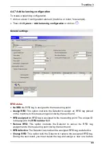
Detector display this name can only contain 5 characters.
Enter the radius in mm for which balancing weights can be applied to the rotor.
The Detector uses this value to calculate a suggested test weight (see notes in
section "Balancing measurement"
). If you enter 0 here, the Detector cannot
calculate a suggested test weight.
Deactivate
Continuous
if you can attach the balancing weights anywhere on the
shaft. If this is not possible (e.g. with a fan with 10 blades),
Continuous
must
not be selected.
If you activated
Continuous
, use
Discrete
positions
to select the number of
possible positions for the balancing weights, e.g. for a fan. In addition, please
enter the angle of the next possible position against the direction of rotation to
the reflex mark edge in
Angle trigger mark
-> Pos. 1.
This position is called
P1.
Resonance frequency bands
In this section you can manually enter the resonant frequency bands determined
for this measuring point.
Click on
.
Enter the name of the frequency band.
Select the
Start frequency
and
End frequency
and
then click
OK
.
You can copy resonant frequency b ands determined from a run up/
coast down test and sub sequent creation of an amplitude/phase
diagram to the b alancing configuration (see Setup run up/coast
down
).
To delete frequency bands
select a frequency band .
Click on
and
confirm with
Yes
.
234
82