


245
Detector III
You can now restrict the calculated suggested weight to the particular safety limit.
The following input of the weights actually applied remains unaffected by this.
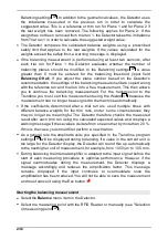
Now the weights have to be attached. If you attach weights different from the
suggested values (e.g. because you do not have the needed weights), please
enter the value of the weights actually attached along with their position. On a 2-
plane balancing job, this step is done separately for every plane. If you are using
discrete positions, the program always displays two weights. Together they equal
the required balancing weight.
You can abort input of weights at any time by pressing
the Esc b utton
in order
to use to the vector calculator, for example. When you click
Apply weight
again,
the previous inputs are still there, so you can continue at the same point.
Here again, weight positions are counted AGAINST the direction of
rotation starting from the set edge of the trigger mark.
The coefficients calculated and b alance weights entered are saved
together as part of the sub sequent Trim run
. This data can only
b e read out using Trendline once the trim run has b een carried out
and the
Values are OK
confirmation has b een provided with
the
Enter button
.
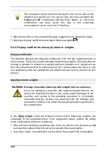
6.8.5 Trim run
To perform the trim run select
Trim run
.
Attach the sensors to the component and connect these to the BNC connectors
of the Detector as specified in the balancing configuration
.
The Detector guides you through the measurement and determines the
amplitude and phase of the vibration at the sensor positions as well as the
245
69