2.1.1.1 Paper Feeding
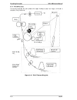
Paper can be fed into the printer from the paper feed tray (150 sheets) or from the manual feed slot
(1 sheet at a time). Installing an optional second paper feed unit (lower cassette, 250 sheets) adds
another feeding method. Paper fed by the paper take-up roller is transported to the transport roller,
pre-image transfer roller, and then exit roller. After this, the paper is fed out onto the print tray. The
starting position of an image is decided by the paper take-up sensor (PC1). A photo sensor is used
as the paper take-up sensor (PC1) and the paper exit sensor (PC3).
Paper Feeding Tray (Standard Tray)
When the paper take-up solenoid is energized, the main motor (M1) drive is transmitted to the
paper take-up roller via the paper take-up clutch (a one-way clutch) to rotate the paper take-up
roller one revolution. At the same time, the depression cam rotates and releases the paper lift-up
plate to feed the top (first) paper. The fixed separating pad is used for the paper separation system.
It prevents the second or later sheets from being fed together with the top paper.
Upper Fusing Roller
Paper Exit Roller
Lower
Fusing
Roller
PC Drum
Pre-Image Transfer
Roller
Paper Lift-Up Plate
Fixed Separating
Pad
Transport Roller
Paper Take-Up Sensor (PC1)
Paper Exit Sensor
(PC3)
Paper Take-Up
Roller
Depression
Cam
Paper Take-
Up Clutch
Paper Take-Up
Solenoid (SL1)
When SL1 is de-energized
When SL1 is energized
Paper Lift-Up Plate
Paper
Figure 2-3. Paper Feeding from the Paper Feed Tray
EPL-5500 Service Manual
Operating Principles
Rev. B
2-3
Summary of Contents for EPL-5500
Page 1: ...EPSON TERMINAL PRINTER EPL 5500 SERVICE MANUAL EPSON 4005431 ...
Page 2: ... ii ...
Page 12: ...Rev A 1 iii ...
Page 62: ...EPL 5500 Service Manual Operating Principles Rev B 2 11 ...
Page 122: ...6 ii Rev A ...
Page 125: ...EPL 5500 Service Manual Maintenance Rev B 6 3 ...
Page 142: ...Figure A 8 C169 MAIN B Component Layout Rear EPL 5500 Service Manual Appendix Rev A A 17 ...
Page 144: ......
Page 145: ...EPSON ...

