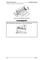
ASSEMBLY POINTS
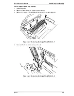
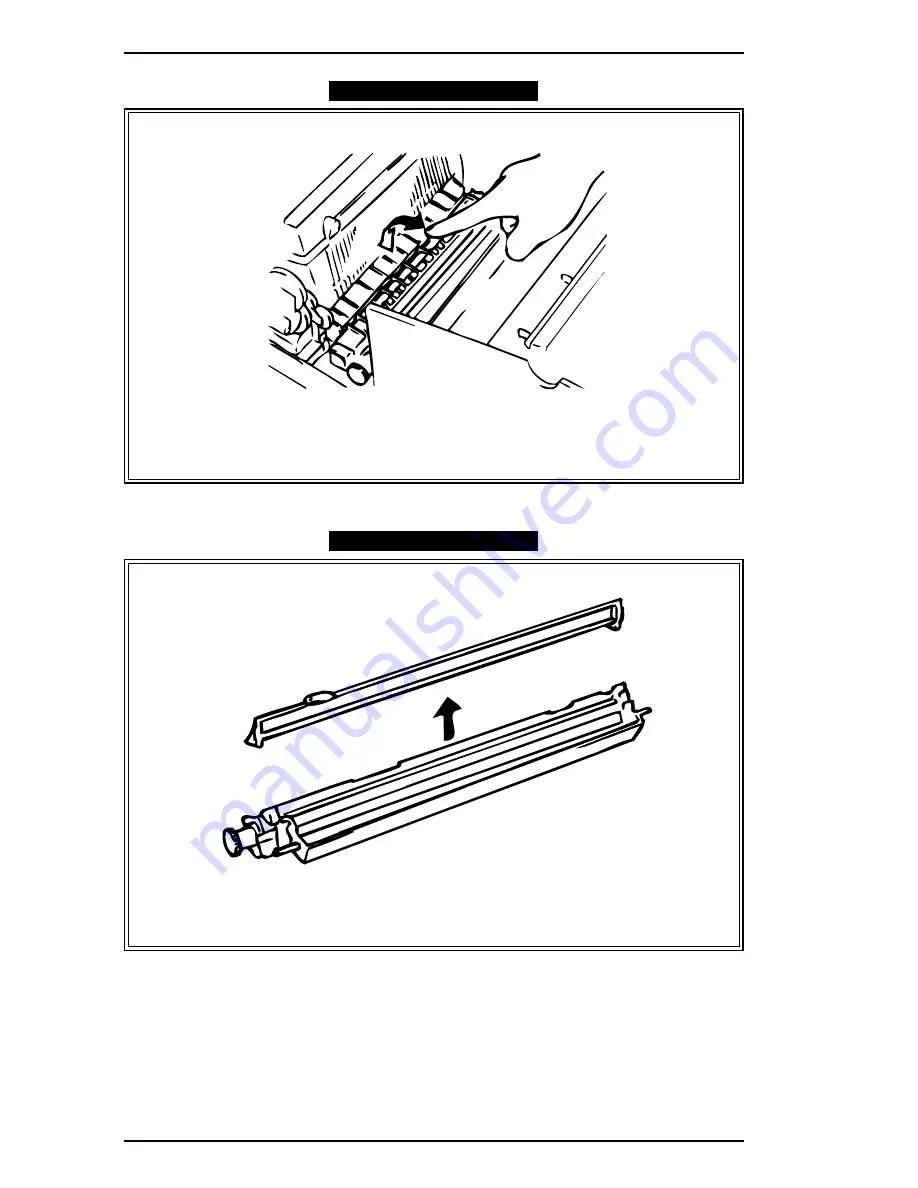
After reinstalling the image transfer unit, check that the unit smoothly moves up and
down.
5.
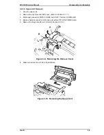
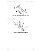
Remove the remove the electrode comb.
ASSEMBLY POINTS
When reinstalling the electrode comb, be careful of the direction of installation. Install the
electrode comb so that the terminal of the comb faces the image transfer roller drive gear.
Figure 3-7. Moving the Image Transfer Unit
Figure 3-8. Reinstalling the Electrode Comb
Disassembly and Assembly
EPL-5500 Service Manual
3-8
Rev. B
Summary of Contents for EPL-5500
Page 1: ...EPSON TERMINAL PRINTER EPL 5500 SERVICE MANUAL EPSON 4005431 ...
Page 2: ... ii ...
Page 12: ...Rev A 1 iii ...
Page 62: ...EPL 5500 Service Manual Operating Principles Rev B 2 11 ...
Page 122: ...6 ii Rev A ...
Page 125: ...EPL 5500 Service Manual Maintenance Rev B 6 3 ...
Page 142: ...Figure A 8 C169 MAIN B Component Layout Rear EPL 5500 Service Manual Appendix Rev A A 17 ...
Page 144: ......
Page 145: ...EPSON ...


