2.1 ENGINE OPERATION
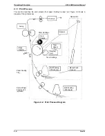
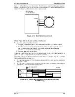
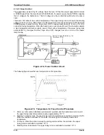
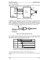
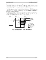
This section describes the functions and operating principles of the EPL-5500 engine. Figure 2-1
shows the locations and names of the main engine components.
1.
Fan Motor (M3)
11. Paper Feeding Tray
2.
Lower Fusing Roller
12. Paper Lift-up Plate
3.
Paper Exit Sensor (PC3)
13. Paper Empty Sensor (PI1)
4.
Upper Fusing Roller
14. Paper Take-up Roller
5.
Heater Lamp (H1)
15. Paper Transport Roller
6.
Paper Exit Roller
16. Paper Take-up Sensor (PC1)
7.
Print Tray
17. Pre-image Transfer Roller
8.
Optical Unit
18. Electrode Comb
9.
Toner Cartridge
19. Drum Cartridge
10. Manual Feed Guide
Optional Second Paper
Feeding Unit
1
2
3
4
5
6
7
8
9
10
11
12
13
14
15
16
17
18
19
Figure 2-1. Main Components
EPL-5500 Service Manual
Operating Principles
Rev. B
2-1
Summary of Contents for EPL-5500
Page 1: ...EPSON TERMINAL PRINTER EPL 5500 SERVICE MANUAL EPSON 4005431 ...
Page 2: ... ii ...
Page 12: ...Rev A 1 iii ...
Page 62: ...EPL 5500 Service Manual Operating Principles Rev B 2 11 ...
Page 122: ...6 ii Rev A ...
Page 125: ...EPL 5500 Service Manual Maintenance Rev B 6 3 ...
Page 142: ...Figure A 8 C169 MAIN B Component Layout Rear EPL 5500 Service Manual Appendix Rev A A 17 ...
Page 144: ......
Page 145: ...EPSON ...


