


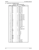
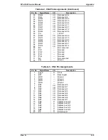
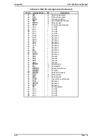
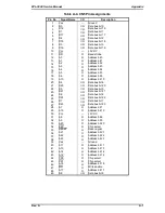
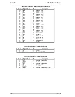


A.1 CONNECTOR PIN ASSIGNMENTS
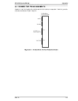
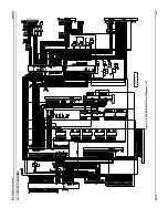
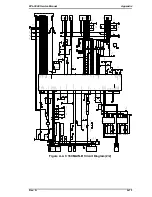
Figures A-1 and A-2 illustrate the interconnection of the primary components. Table A-1 gives the
size and a description of each connector.
CN1
Parallel I/F
CN2
RAM SIMM
CN4
LocalTalk/Serial I/F
module or Type-B EX
ROM SIMM
CN5
C169 MAIN-B Boad
Video Controller Section
Figure A-1. Connections for the Video Controller
EPL-5500 Service Manual
Appendix
Rev. A
A-1
Summary of Contents for EPL-5500
Page 1: ...EPSON TERMINAL PRINTER EPL 5500 SERVICE MANUAL EPSON 4005431 ...
Page 2: ... ii ...
Page 12: ...Rev A 1 iii ...
Page 62: ...EPL 5500 Service Manual Operating Principles Rev B 2 11 ...
Page 122: ...6 ii Rev A ...
Page 125: ...EPL 5500 Service Manual Maintenance Rev B 6 3 ...
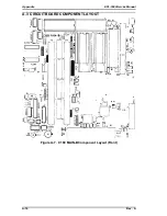
Page 142: ...Figure A 8 C169 MAIN B Component Layout Rear EPL 5500 Service Manual Appendix Rev A A 17 ...
Page 144: ......
Page 145: ...EPSON ...