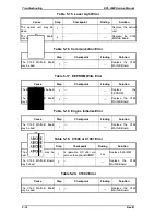
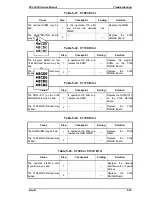
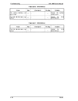

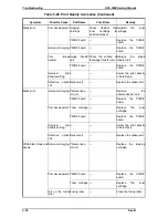
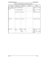


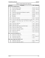
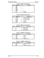


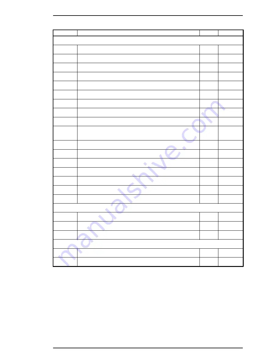
Table A-1. Board Connector Summary
Connector
Description
Pins
Reference
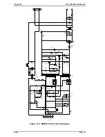
Main Board (C169 MAIN-B Board)
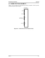
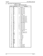
CN1
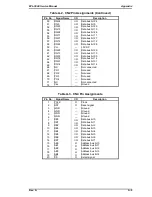
Centronics parallel interface
36 pins
Table 1-8
CN2
Connector for RAM SIMM
72 pins
Table A-2
CN3
(Not used)
20 pins
—
CN4
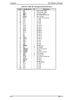
Connector for LocalTalk/Serial I/F Module or Type-B EX
60 pins
Table A-3
CN5
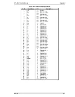
Connector for ROM SIMM
72 pins
Table A-4
CN6
(Not used)
80 pins
—
CN7
(Not used)
40 pins
—
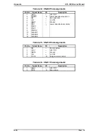
CN202
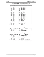
Connector for thermistor
2 pins
Table A-5
CN203
Connector for paper take-up solenoid and paper take-up sensor 6 pins
Table A-6
CN204
Connector for high-voltage supply board (PWB-S and PWB-F
board)
8 pins
Table A-7
CN205
Connector for optical unit
7 pins
Table A-8
CN206
Connector for motor
4 pins
Table A-9
CN207
Connector for power supply board (PWB-E board)
5 pins
Table A-10
CN208
Connector for paper exit sensor
3 pins
Table A-11
CN209
Connector for lower paper cassette
12 pins
Table A-12
CN210
Connector for optical unit
5 pins
Table A-13
CN211
Connector for fan
2 pins
Table A-14
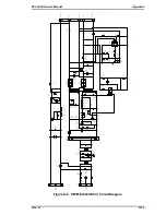
Power Supply Board (PWB-E Board)
CN1
Connector for AC power inlet
4 pins
—
CN2
Connector for main board
5 pin
Table A-11
CN3
Connector for heater lamp
3 pins
—
High-Voltage Supply Board (PWB-F Board)
CN1
Connector for main board
8 pins
Table A-7
CN2
Connector for paper take-up sensor
3 pins
—
EPL-5500 Service Manual
Appendix
Rev. A
A-3
Summary of Contents for EPL-5500
Page 1: ...EPSON TERMINAL PRINTER EPL 5500 SERVICE MANUAL EPSON 4005431 ...
Page 2: ... ii ...
Page 12: ...Rev A 1 iii ...
Page 62: ...EPL 5500 Service Manual Operating Principles Rev B 2 11 ...
Page 122: ...6 ii Rev A ...
Page 125: ...EPL 5500 Service Manual Maintenance Rev B 6 3 ...
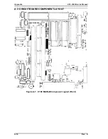
Page 142: ...Figure A 8 C169 MAIN B Component Layout Rear EPL 5500 Service Manual Appendix Rev A A 17 ...
Page 144: ......
Page 145: ...EPSON ...