EPSON AcuLaser C2000 / AcuLaser C1000
Revision E
Disassembly and Assembly
Disassembling Procedure
152
4.2.7 High Voltage Board (HV1, HV2) Removal
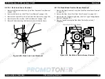
4.2.7.1 HV1 (High Voltage Board) Removal
1. Remove the Rear Controller Cover. (See “Rear Controller Cover Removal”
on page -145.)
2. Remove the Rear Cover. (See “Rear Cover Removal” on page -146.)
3. Remove the Controller Box. (See "Controller Box Removal" on page 150.)
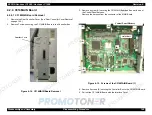
4. Remove 6 connectors, 2 screws, and 4 board supports from the HV1
Board.
5. Remove the insulation sheet under the HV1.
Figure 4-21. HV1 (High Voltage Board) Removal
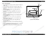
4.2.7.2 HV2 (High Voltage Board) Removal
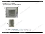
1. Remove the Rear Controller Cover. (See “Rear Controller Cover Removal”
on page -145.)
2. Remove the Rear Cover. (See “Rear Cover Removal” on page -146.)
3. Disconnect the twenty 9 connectors from the MCU and discharge harness
for the HV2 and the transfer roller from the transfer roller.
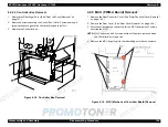
4. Remove 2 screws securing the PWB-A support plate to the printer frame.
5. Remove 2 screws securing the PWB-A and Controller Box. (See
"Controller Box Removal" on page 150.)
6. Remove the PWB-A support plate.
7. Remove 2 connectors, 3 board supports, and 1 screw from the PPWB-A
support plate, and remove the HV2 Board.
Figure 4-22. PWB-A Support Plate Removal
C H E C K
P O I N T
The D terminal on the HV1 is not used.
Summary of Contents for ACULASER COLOR 1000
Page 1: ...EPSON ACULASERCOLOR2000 ACULASERCOLOR1000 A4 Color Laser Printer SEPG00004 SERVICE MANUAL ...
Page 12: ...C H A P T E R 1 PRODUCTDESCRIPTIONS ...
Page 68: ...C H A P T E R 2 OPERATINGPRINCIPLES ...
Page 104: ...C H A P T E R 3 TROUBLESHOOTING ...
Page 138: ...C H A P T E R 4 DISASSEMBLYANDASSEMBLY ...
Page 182: ...C H A P T E R 5 ADJUSTMENT ...
Page 187: ...C H A P T E R 6 MAINTENANCE ...
Page 189: ...C H A P T E R 7 APPENDIX ...
Page 191: ......
Page 192: ......
Page 220: ......
Page 221: ......
Page 222: ......
Page 223: ......
Page 224: ......
Page 225: ......
Page 226: ......
Page 227: ......
Page 228: ......
Page 229: ......
Page 230: ......


