EPSON AcuLaser C2000 / AcuLaser C1000
Revision E
Troubleshooting
Printer Message
129
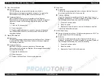
Main Motor is abnormal
Detection of transportation motor (M1) rotation is detected 1 second after
transportation motor (M1) starts rotating until the transportation motor (M1)
stops.
When the transportation motor M_Lock signal becomes active for 0.5 seconds,
the printer detects that the transportation motor is abnormal.
Fusing Motor is abnormal
Detection of fusing motor (M4) rotation is detected 1 second after fusing motor
(M4) starts rotating until the fusing motor (M4) stops.
When the fusing motor M_Lock signal becomes active for 0.5 seconds, the
printer detects that the fusing motor is abnormal.
Fusing Pressure / Estrangement is abnormal
When one of the following items is detected, the printer detects that the driving
motor is abnormal.
1. When the pressure state is not detected 4 seconds after the printer starts
pressure roller to pressure.
2. When the estrangement state is not detected 4 seconds after the printer
starts pressure roller to estrange.
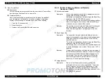
No.
Check Item
Solution
1
Does the transportation motor
(M1) rotate during printing?
No
Remove connector PJ21A and insert
it again.
Yes
Check that no weight applies on the
each roller or gears.
Others
Replace PWB-A.
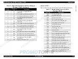
No.
Check Item
Solution
1
Does the fusing motor (M4)
rotate during printing?
No
Remove connector PJ22A and insert
it again.
Yes
Check that no weight applies on the
each roller or gears.
Others
Replace PWB-A.
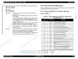
No.
Check Item
Solution
1
Does the fusing unit upshot?
Yes
Install the fusing unit correctly.
2
Does the fusing pressure motor
(M5) rotate? Check by its sound.
No
Remove connector PJ25A and insert
it again.
Replace fusing pressure motor.
Yes
Replace the fusing pressure position
sensor.
Replace the pressure roller
estrangement sensor.
Others
Replace PWB-A.
Summary of Contents for ACULASER COLOR 1000
Page 1: ...EPSON ACULASERCOLOR2000 ACULASERCOLOR1000 A4 Color Laser Printer SEPG00004 SERVICE MANUAL ...
Page 12: ...C H A P T E R 1 PRODUCTDESCRIPTIONS ...
Page 68: ...C H A P T E R 2 OPERATINGPRINCIPLES ...
Page 104: ...C H A P T E R 3 TROUBLESHOOTING ...
Page 138: ...C H A P T E R 4 DISASSEMBLYANDASSEMBLY ...
Page 182: ...C H A P T E R 5 ADJUSTMENT ...
Page 187: ...C H A P T E R 6 MAINTENANCE ...
Page 189: ...C H A P T E R 7 APPENDIX ...
Page 191: ......
Page 192: ......
Page 220: ......
Page 221: ......
Page 222: ......
Page 223: ......
Page 224: ......
Page 225: ......
Page 226: ......
Page 227: ......
Page 228: ......
Page 229: ......
Page 230: ......


