DVC6200f Digital Valve Controller
November 2010
150
AO
PID2
PID1
Splitter
BK_CAL_IN
CAS-IN
OUT
BK_CAL_OUT
BK_CAL_IN2
BK_CAL_IN1
BK_CAL_OUT
BK_CAL_OUT
CAS-IN
CAS-IN
OUT2
OUT1
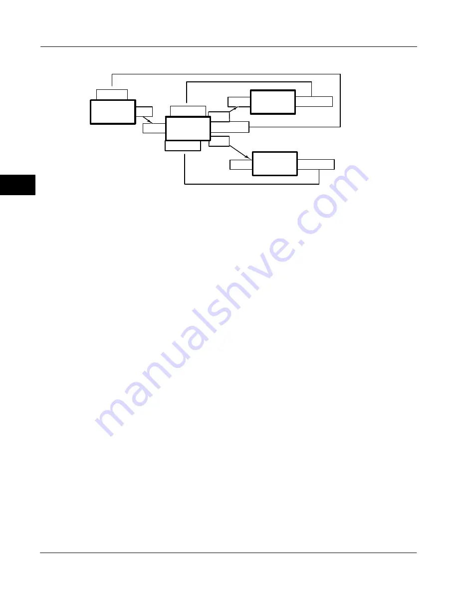
Figure 4-21. Output Splitter Configuration
Splitter = Split range function block being described.
AO = Receiver of OUT_1 for 0
−
50% range of SP
PID2 = Receiver of OUT_2 for 50
−
100% range of SP
CAS_IN of the Splitter receives the OUT of PID1.
BKCAL_IN of PID1 receives BKCAL_OUT of the
Splitter. CAS_IN of the AO receives OUT_1 of the
Splitter and PID2 receives OUT_2 of the Splitter.
BKCAL_IN_1 of the Splitter receives BKCAL_OUT of
the AO and BKCAL_IN_2 of the Splitter receives
BKCAL_OUT of PID2.
The discussion in this section defines the behavior
which is used to handle the initial value calculation
and status which can in turn be sent to PID1. This
behavior is defined in such a way that no “bumps” are
generated by changing modes, and that PID1 does not
wind up.
The splitter utilizes special handling for cascade
initialization because it has two independent outputs.
When a downstream block indicates to the splitter that
it wants to initialize, by asserting IR (initialization
request) on its BKCAL_OUT, one of two things
happens. Under some circumstances, it is possible to
pass an initialization request from a downstream block
back up to the block upstream of the splitter, so that
all three blocks balance for bumpless transfer to
cascade mode. Otherwise, the requested splitter
output goes to the requested value by placing an
internal offset between that output and the output of
the curve, and then ramping that offset to zero in
BAL_TIME seconds after the cascade is made up.
The splitter normally runs with both outputs connected
to blocks in cascade mode. If one or both of the blocks
is not in cascade mode, special limiting action is taken.
Specifically, if one block indicates that it is not in
cascade by NI (not invited) status on its BKCAL_OUT,
then the BKCAL_OUT of the splitter asserts limits at
the range extremes of the block that is still in cascade
mode. Even if the upstream controller does not want
to operate in that range, there will be no reset windup
when it can move into the range. If both downstream
blocks show NI, then the splitter can only wait until
one of them requests cascade initialization.
BKCAL_OUT of the splitter can hold the upstream
block at the value of the SP. The actual mode is IMan.
When cascade initialization is requested, by IR
substatus on a BKCAL_IN, it is first necessary to
determine if the other BKCAL_IN has NI substatus. If
so, the value at the BKCAL_IN asserting IR is taken
as the Y value for its curve, and the resulting X value
is sent on BKCAL_OUT to PID1. If the other substatus
is OK, then the internal offset and BAL_TIME is used.
If both blocks have IR substatus, then one output is
processed until its cascade is closed. The choice is
based on the presence of limit status in BKCAL_IN. If
BKCAL_IN_1 is limited, then if BKCAL_IN_2 is not
limited then OUT_2 is processed first, else OUT_1 is
processed first.
Cascade initialization is also required when the block
transitions from Auto to Cas mode. This action is
identical to that described for the PID block.
The required actions are summarized in table 4-47.
4
Summary of Contents for FIELDVUE DVC6200f
Page 42: ...DVC6200f Digital Valve Controller November 2010 30 4 ...
Page 60: ...DVC6200f Digital Valve Controller November 2010 48 4 ...
Page 108: ...DVC6200f Digital Valve Controller November 2010 96 4 ...
Page 122: ...DVC6200f Digital Valve Controller November 2010 110 4 ...
Page 188: ...DVC6200f Digital Valve Controller November 2010 176 4 ...
Page 200: ...DVC6200f Digital Valve Controller November 2010 188 4 ...
Page 216: ...DVC6200f Digital Valve Controller November 2010 204 5 ...
Page 250: ...DVC6200f Digital Valve Controller November 2010 238 8 ...
Page 254: ...DVC6200f Digital Valve Controller November 2010 242 A ...
Page 284: ...DVC6200f Digital Valve Controller November 2010 272 D ...
Page 290: ...DVC6200f Digital Valve Controller November 2010 278 E ...
Page 308: ...DVC6200f Digital Valve Controller November 2010 296 F ...
Page 312: ...DVC6200f Digital Valve Controller September 2010 300 Notes G Glossary ...
Page 324: ...DVC6200f Digital Valve Controller November 2010 312 F Index ...


