


DVC6200f Digital Valve Controller
November 2010
180
Auto—On failure of a remote cascade connection, the
block sets the target mode to Auto, if permitted.
Man—On failure of remote cascade connection, the
block sets the target mode to Man, if permitted.
The user may configure SHED_OPT [23] so that it
calls for a target mode that is not permitted. When
doing this, the mode logic uses the following rules as
applied by the remote logic:
Shed logic never results in a non-permitted target
mode.
Shed logic never attempts to attain an actual
mode of Auto or Cas if that mode is not permitted.
Block Initialization
The Fieldbus Foundation specification requires that
certain parameters have initial values of uninitialized in
function blocks. In addition to setting the Resource
block mode to AUTO, the control system or the user
must change those parameters from their uninitialized
value to a valid value in order for the function block to
move from the Out of Service mode. For the DO
function block, the parameters that must be initialized
are:
SHED_OPT [23] (see page 4-151 for valid values)
CHANNEL [18]
Status Handling
Under normal operating conditions, the status of
OUT_D [9] is Good Non-Cascade, and the status of
BKCAL_OUT_D [21] is Good:Cascade. If the output
hardware fails, the status of BKCAL_OUT_D [21] is
set to Bad:Device Fail, and the BLOCK_ERR [6]
shows Output Failure. If the hardware used for output
feedback fails, the status of READBACK_D [16] and
PV_D [7] is set to Bad:DeviceFail, and the
BLOCK_ERR [6] shows Process Variable has Bad
Status. If the transducer block mode is Out of Service,
the status of READBACK_D [16] and PV_D [7] is set
to Bad:Out of Service.
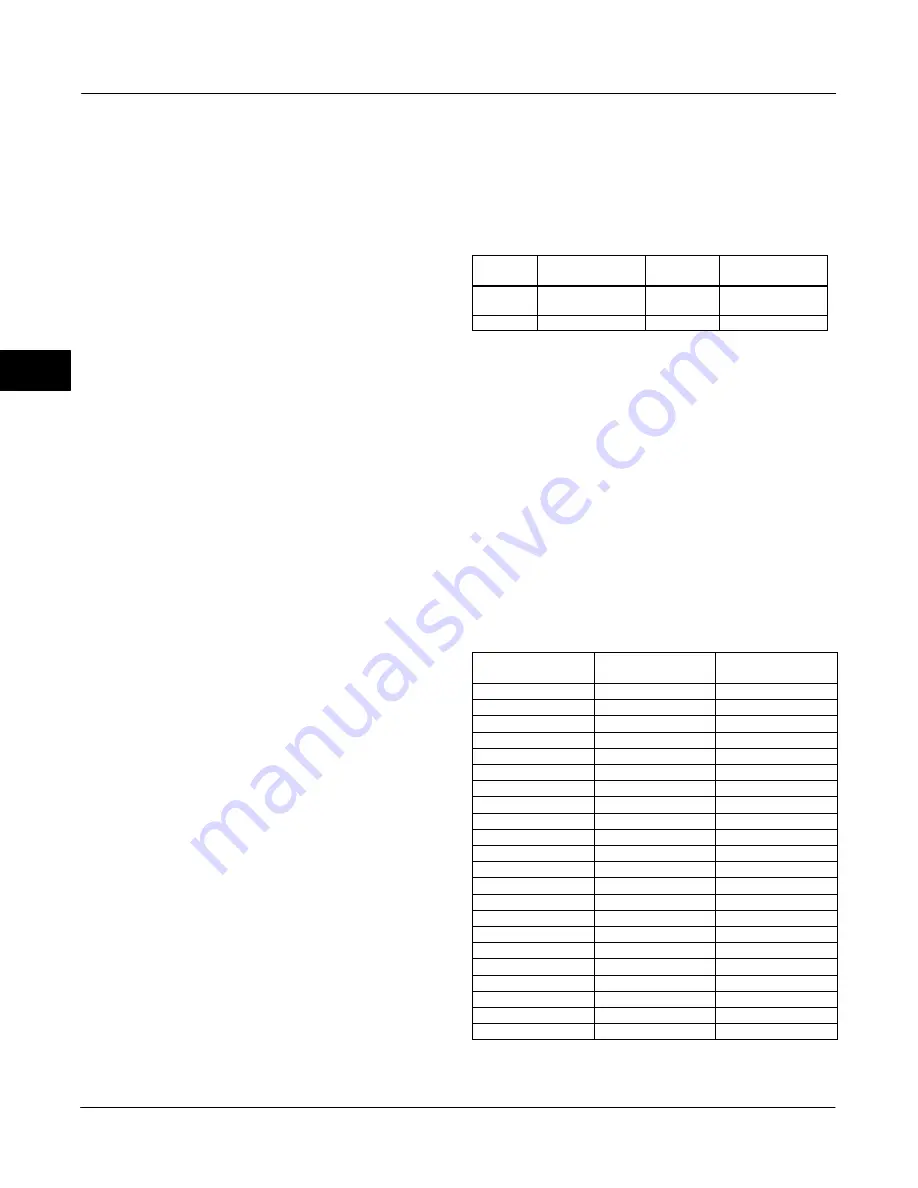
I/O Selection
To select the I/O associated with the discrete output,
configure the value of the CHANNEL [18] parameter.
Table 4-69 lists the valid Channel selections for the
DO block.
Table 4-69. Channel Selections for the Discrete Output
Function Block
Selection
Transducer Block
Parameter
Transducer
block Index
Description
22
SETPOINT_D
32
Discrete Valve
Control
0
−
−
Uninitialized
Setting the Output
To set the output for the DO block, you must first set
the mode to define the manner in which the block
determines its set point and output. In Cascade mode,
the set point equals the input value at the CAS_IN_D
[17] parameter. In Automatic or Manual mode, the set
point must be entered manually by the user. For
Automatic, the value must be written to the SP_D [8]
parameter and for Manual, the value must be written
to OUT_D [9]. In Remote Cascade mode, the set point
is determined by a host computer that is writing to the
RCAS_IN_D [22] parameter. Table 4-70 lists discrete
states used by the digital valve controller for the set
point.
Table 4-70. Valve Set Point for Discrete State
Discrete State
Valve Set Point with
IO_OPTS Invert = 0
Valve Set Point with
IO_OPTS Invert = 1
0
Closed
Open
1
Open
Closed
5
5%
Closed
10
10%
Closed
15
15%
Closed
20
20%
Closed
25
25%
Closed
30
30%
Closed
35
35%
Closed
40
40%
Closed
45
45%
Closed
50
50%
Closed
55
55%
Closed
60
60%
Closed
65
65%
Closed
70
70%
Closed
75
75%
Closed
80
80%
Closed
85
85%
Closed
90
90%
Closed
95
95%
Closed
100
Open
Closed
To further customize the output, configure the
following supported I/O options: SP tracks PV in Man,
4
Summary of Contents for FIELDVUE DVC6200f
Page 42: ...DVC6200f Digital Valve Controller November 2010 30 4 ...
Page 60: ...DVC6200f Digital Valve Controller November 2010 48 4 ...
Page 108: ...DVC6200f Digital Valve Controller November 2010 96 4 ...
Page 122: ...DVC6200f Digital Valve Controller November 2010 110 4 ...
Page 188: ...DVC6200f Digital Valve Controller November 2010 176 4 ...
Page 200: ...DVC6200f Digital Valve Controller November 2010 188 4 ...
Page 216: ...DVC6200f Digital Valve Controller November 2010 204 5 ...
Page 250: ...DVC6200f Digital Valve Controller November 2010 238 8 ...
Page 254: ...DVC6200f Digital Valve Controller November 2010 242 A ...
Page 284: ...DVC6200f Digital Valve Controller November 2010 272 D ...
Page 290: ...DVC6200f Digital Valve Controller November 2010 278 E ...
Page 308: ...DVC6200f Digital Valve Controller November 2010 296 F ...
Page 312: ...DVC6200f Digital Valve Controller September 2010 300 Notes G Glossary ...
Page 324: ...DVC6200f Digital Valve Controller November 2010 312 F Index ...


