


DI Function Block
November 2010
193
Table 4-80. BLOCK_ERR Conditions
Condition
Number
Condition Name and Description
0
Other (N/A)
1
Block Configuration Error—CHANNEL set to 0 through 10
(uninitialized)
2
Link Configuration Error (N/A)
3
Simulate Active—Simulate is enabled. Output does not
reflect process conditions
4
Local Override (N/A)
5
Device Fault State Set (N/A)
6
Device Needs Maintenance Soon (N/A)
7
Input failure/process variable has Bad status—The
hardware is bad or the transducer block mode is Out of
Service
8
Output Failure (N/A)
9
Memory Failure (N/A)
10
Lost Static Data (N/A)
11
Lost NV Data (N/A)
12
Readback Check Failed (N/A)
13
Device Needs Maintenance Now (N/A)
14
Power Up—Set after power-up until actual mode is not Out of
Service
15
Out of Service—The actual mode is Out of Service (OOS).
The block is not being processed.
Action on Failure
In case of hardware failure, FIELD_VAL_D [17], PV_D
[7], and OUT_D [8] change to a Bad status and the
BLOCK_ ERR [6] parameter shows Process Variable
has Bad Status. If the transducer block mode is Out of
Service, the status of FIELD_VAL_D [17], PV_D [7],
and OUT_D [8] is set to Bad:Out of Service.
Simulation
To support testing of the control strategy, you can
enable the SIMULATE_D [9] parameter. Normally the
measurement value and status used for
FIELD_VAL_D [17] in the DI block reflect actual
process values as provided by the transducer block.
When the SIMULATE_D [9] parameter is enabled,
value and status used for FIELD_VAL_D [17] is
supplied by the user manually. To enable simulation in
the DI function block, the simulate jumper must be
installed. For information on the installation of this
jumper, see the Installation section.
The SIMULATE_D [9] parameter has three
components:
Simulate_D enable/disable determines whether
the function block will use the actual process value
and status, or Simulate Value and Simulate Status.
Transducer Value and Status reflect the process
values provided by the transducer block.
Simulate Value and Status may be entered by
the user when enable/disable is set to enabled.
To use simulate, first install the simulate jumper in the
terminal box, then set Simulate_D enable/disable to
enabled, then enter the desired values for Simulate
Value and Status.
When SIMULATE_D [9] is enabled, the Simulate
Active bit of the BLOCK_ERR [6] parameter is set
(refer to the Block Errors description). When the
simulate jumper is installed, the Simulate Jumper bit of
the transducer block parameter SELFTEST_STATUS
[78] is set.
Application Information
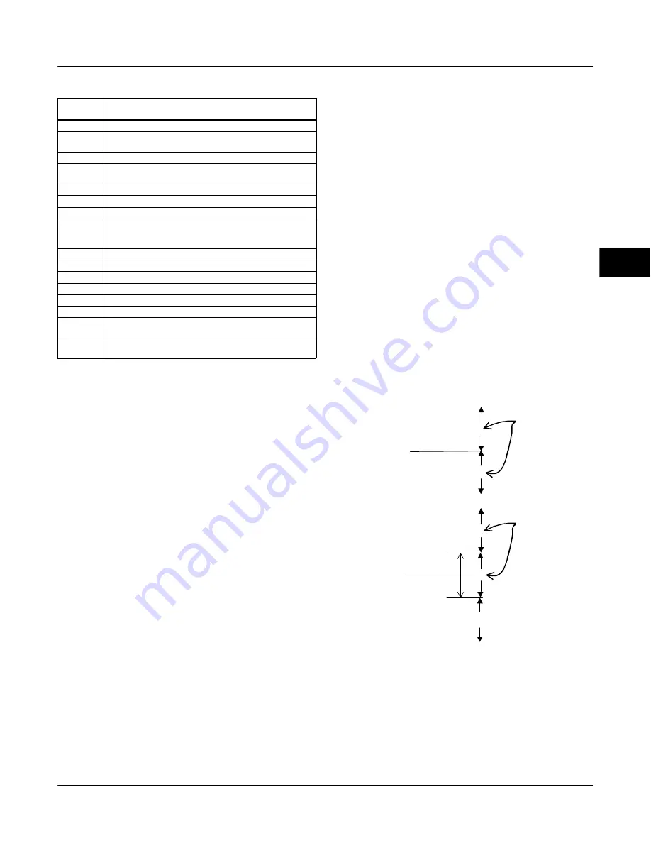
Figure 4-31 compares the operation of a standard
discrete input to a proximity discrete input. With the
standard discrete input, the discrete input changes
state when the valve position passes a configurable
trip point. This can be used to indicate if the valve
position is above or below the trip point.
Configurable
Band
DISCRETE INPUT
VALUE
0
0
1
0
1
STANDARD DISCRETE INPUT
PROXIMITY DISCRETE INPUT
DISCRETE INPUT
VALUE
Figure 4-31. Proximity Discrete Input Compared to a Standard
Discrete Input
With the proximity discrete input a configurable band
can be established about a central point. Whenever
the valve position enters this configurable band, the
discrete input changes state. A proximity discrete input
is useful for applications which require knowing the
location of the valve when the valve is not near 0% or
100%.
4
Summary of Contents for FIELDVUE DVC6200f
Page 42: ...DVC6200f Digital Valve Controller November 2010 30 4 ...
Page 60: ...DVC6200f Digital Valve Controller November 2010 48 4 ...
Page 108: ...DVC6200f Digital Valve Controller November 2010 96 4 ...
Page 122: ...DVC6200f Digital Valve Controller November 2010 110 4 ...
Page 188: ...DVC6200f Digital Valve Controller November 2010 176 4 ...
Page 200: ...DVC6200f Digital Valve Controller November 2010 188 4 ...
Page 216: ...DVC6200f Digital Valve Controller November 2010 204 5 ...
Page 250: ...DVC6200f Digital Valve Controller November 2010 238 8 ...
Page 254: ...DVC6200f Digital Valve Controller November 2010 242 A ...
Page 284: ...DVC6200f Digital Valve Controller November 2010 272 D ...
Page 290: ...DVC6200f Digital Valve Controller November 2010 278 E ...
Page 308: ...DVC6200f Digital Valve Controller November 2010 296 F ...
Page 312: ...DVC6200f Digital Valve Controller September 2010 300 Notes G Glossary ...
Page 324: ...DVC6200f Digital Valve Controller November 2010 312 F Index ...


