13
Power Connection
6.3
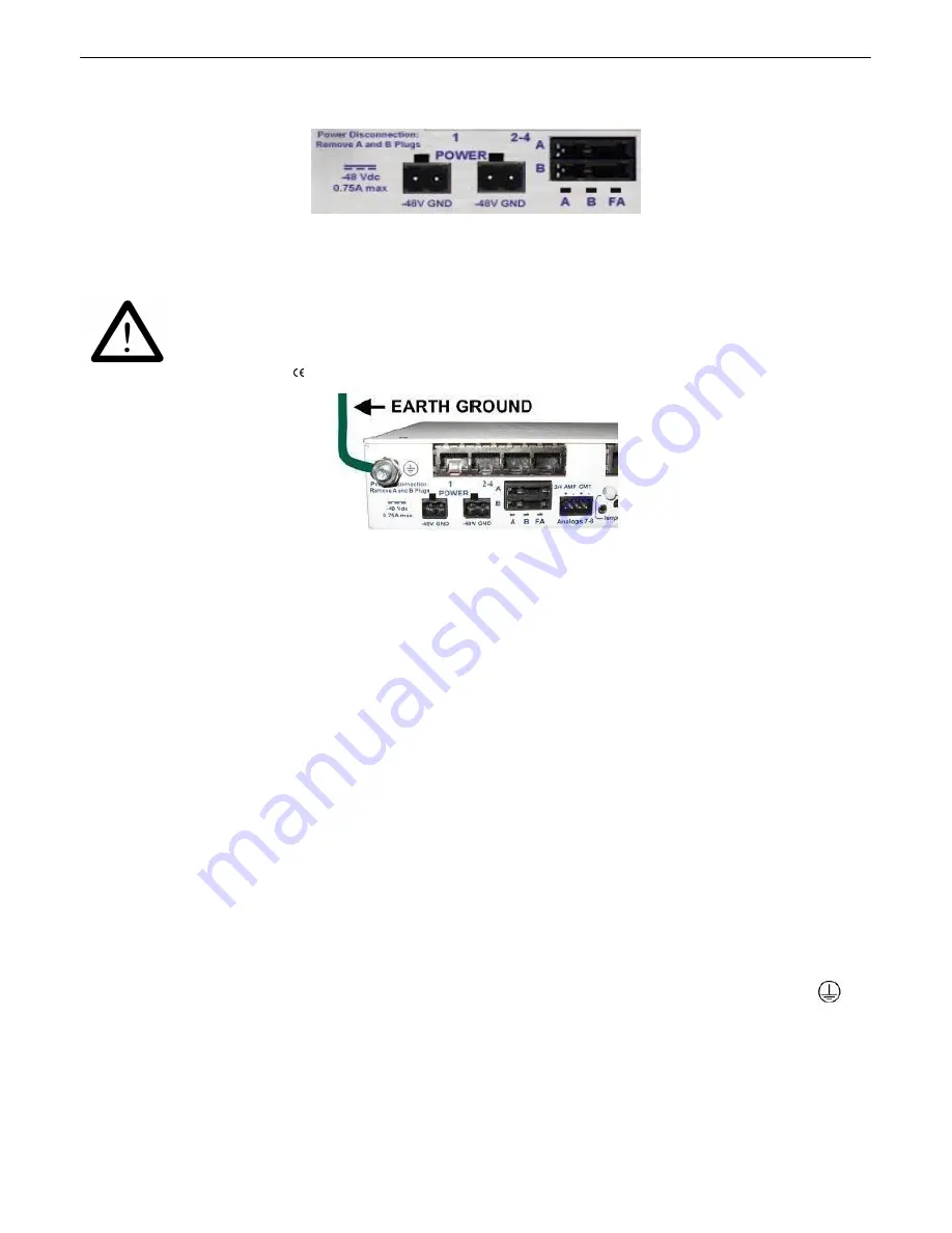
Fig. 6.3.1.
Power connectors and fuse.
The NetGuardian has two screw terminal barrier plug power connectors, located on the left side of the
back panel. (See Figure 6.3.1.)
WARNING!
The Grounding Lug on the back of the unit provides a permanent connection to
earth ground when connected. The Grounding Lug must be used in order to
comply with standards.
Grounding Lug and Symbol
Before you connect a power supply to the NetGuardian, test the voltage of your power supply:
·
Connect the black common lead of a voltmeter to the ground terminal of the battery, and connect
the red lead of the voltmeter to the battery's –48 VDC terminal. The voltmeter should read
between -36 and –72 VDC
. If the reading is outside this range, test the power supply.
·
If your NetGuardian has the -24 VDC power connection option, then the voltmeter should read
between -18 and -36 VDC
.
·
If your NetGuardian has the +12 VDC power connection option, then the voltometer should read
b11 and +18 VDC
.
To connect the NetGuardian to a power supply, follow these steps:
1. Remove the fuse from the back panel of the NetGuardian.
Do not reinsert the fuse until all
connections to the unit have been made.
2. Remove the power connector plug from Power Connector A. Note that the plug can be inserted
into the power connector only one way - this ensures that the barrier plug can only be reinserted
with the correct polarity.
Note
:
that the
–48V terminal is on the left
and the
GND terminal is on the right
.
3. Use the grounding lug to connect the unit to earth ground. The grounding lug is next to the
symbol. Insert the eyelet of the earth ground cable between the two bolts on the grounding lug
(Ground cable not included).
4. Insert a
battery ground
into the power connector plug's
right terminal
and tighten the screw
5. Insert a
–48 VDC
line to the plug's
left terminal
and tighten its screw.
Summary of Contents for NetGuardian 832A
Page 9: ...4 Hardware kit containing a WAGO connector ...
Page 34: ...29 right ...
Page 39: ...34 Fig 6 9 1 Optional 66 block pinout for Discretes 1 24 ...
Page 40: ...35 Fig 6 9 2 Optional 66 block pinout for Analogs 1 8 Discretes 25 32 Relays 1 8 ...
Page 50: ...45 ...
Page 73: ...68 13 2 8 DSCP Configuration Configure your Serial Data Ports through the Edit Ports screen ...
Page 104: ...99 ...
Page 105: ...100 ...
Page 106: ...101 ...


