40
Optional Hinged Pluggable Back Panel
6.12
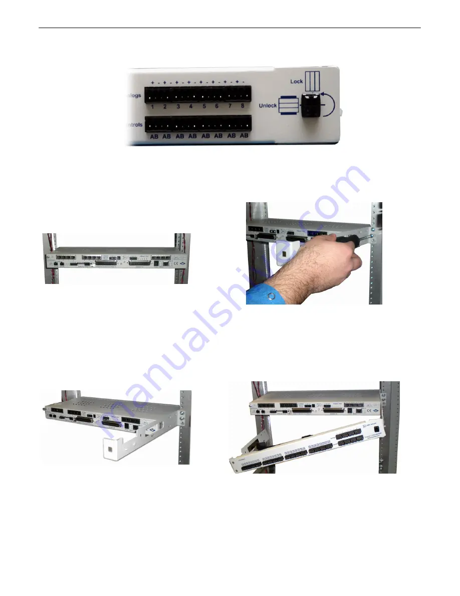
Fig.6.12.1
- Silk screen on the Hinged Pluggable Back Panel indicates
which way to turn the black swivel to lock and unlock the gate.
Instructions for installing the Hinged Pluggable Back Panel:
Rear View
1. To begin installing the hinged
pluggable back panel, the NetGuardian
G5 should be rack mounted.
Suggestion:
Mount the unit in the
flush, rack-mount position. This
means the front of the NetGuardian is
flush with the front of the rack post.
2. Facing the back of the NetGuardian, install the right
side of the hinged pluggable back panel. Used the
screws provided to secure the right mounting arm to
the rack.
3. The rack should appear as shown
above.
4. Close the back panel gate and lock it in place by turning
the black swivel to the vertical, locked position as
indicated on the silk screen (See Figure 6.12.1).
Summary of Contents for NetGuardian 832A
Page 9: ...4 Hardware kit containing a WAGO connector ...
Page 34: ...29 right ...
Page 39: ...34 Fig 6 9 1 Optional 66 block pinout for Discretes 1 24 ...
Page 40: ...35 Fig 6 9 2 Optional 66 block pinout for Analogs 1 8 Discretes 25 32 Relays 1 8 ...
Page 50: ...45 ...
Page 73: ...68 13 2 8 DSCP Configuration Configure your Serial Data Ports through the Edit Ports screen ...
Page 104: ...99 ...
Page 105: ...100 ...
Page 106: ...101 ...


