


14 | © Danfoss | August 2018
AQ00000211
ENGINEERING TOMORROW
OSP
Vehicle speed
sensor
Auto-guidance
MMI
AUX
PLUS+1 Service
tool
Main
Micro-crontroller
Safety
Micro-crontroller
WAS*
Solenoid
valve
bridge
EH valve
Cut-off
valve
Solenoid
valve
LVDT
Cut-off
valve output
Vbat-
CAN_safety
CAN_Main
AD1
AD2
AD3 (not used)
5V sensor
Sensor ground -
P
T
Main spool position
Main spool position
PVED-CLS
Pilot
Pressure
Pilot
Pressure
Vbat +
(9 … 32 V )
Vbat -
Key off/de-energize
Cylinder
+V1
+V2
GND1
GND2
OUT1
OUT2
Wheel
Angle
Sensor
5V sersor supply
Sensor ground -
AD1/CAN
AD2/CAN
Wheel angle sensor diagram
Reaction
Switch
Valve
EHi-H
valve
OSP-valve
WAS*
L
R
P
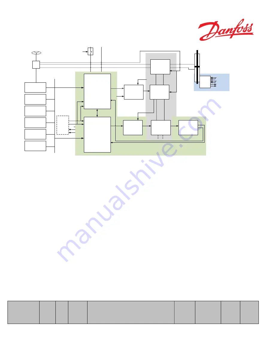
Figure 3 EHi-H System
In a OSPE (Figure 1) and EHi-E (Figure 2) with PVED-CLS, a Danfoss SASA-sensor and a two channel vehicle speed
sensor, a MMI interface (for changing programs, steering devices, steering modes etc.) on the CAN bus are prerequisite
in order to complete the OSPE and EHi-E systems. In an EHi-H system, see figure 3, a two-channel vehicle speed sensor
and an MMI interface (for changing programs, steering devices, steering modes etc.) are prerequisite to complete the
EHi-H system. Depending on the application, up to two auto-guidance controllers and one auxiliary steering device (e.g.
mini-wheel, joystick) can be configured together with the PVED-CLS in an OSPE, EHi-E or EHi-H system.
When the PVED-CLS is mounted on an OSPE/EHi-E/EHi-H the cut-off valve is always present, therefore P3072 needs
to be 255 and the valve type needs to be set to OSPE/EHi-E or EHi-H by setting P3081 to 0 or 2 respectively.
Furthermore OSP displacement, given in ccm, needs to be entered in P3084. If the OSP displacement is unknown, it can
be found on the Danfoss label, located at the end cover of the steering unit.
The cylinder stroke volume is also needed, again in ccm. If effective cylinder volume is unknown, count the steering
wheel turns lock-to-lock and multiply by OSP-displacement, to get the effective cylinder volume. The value needs to be
entered in P3086.
A wheel angle sensor (WAS*), is marked ‘*’ because, either analogue or CAN-based, is required for auto guidance, for
steering wheel soft-stop as well as for EFU and closed loop steering. Danfoss recommend a redundant sensor as
illustrated on Figure 1 & 2, to meet category 3 according to ISO13849.
Name
A
ddr
es
s
D
at
a
ty
pe
U
ni
t
Description of parameter
U
se
r
Range
D
a
n
fo
ss
de
fa
ul
t
val
u
e
S
a
fe
ty
cr
it
ic
a
l
pa
ra
me
t
Summary of Contents for PVED-CLS
Page 6: ...6 Danfoss August 2018 AQ00000211 ENGINEERING TOMORROW ...
Page 71: ... Danfoss August 2018 AQ00000211 71 ENGINEERING TOMORROW Figure 29 ...
Page 127: ... Danfoss August 2018 AQ00000211 127 ENGINEERING TOMORROW ...
Page 147: ... Danfoss August 2018 AQ00000211 147 ENGINEERING TOMORROW ...
Page 182: ...182 Danfoss August 2018 AQ00000211 ENGINEERING TOMORROW ...