93
Chapter 7 - Programming with Serial Communication
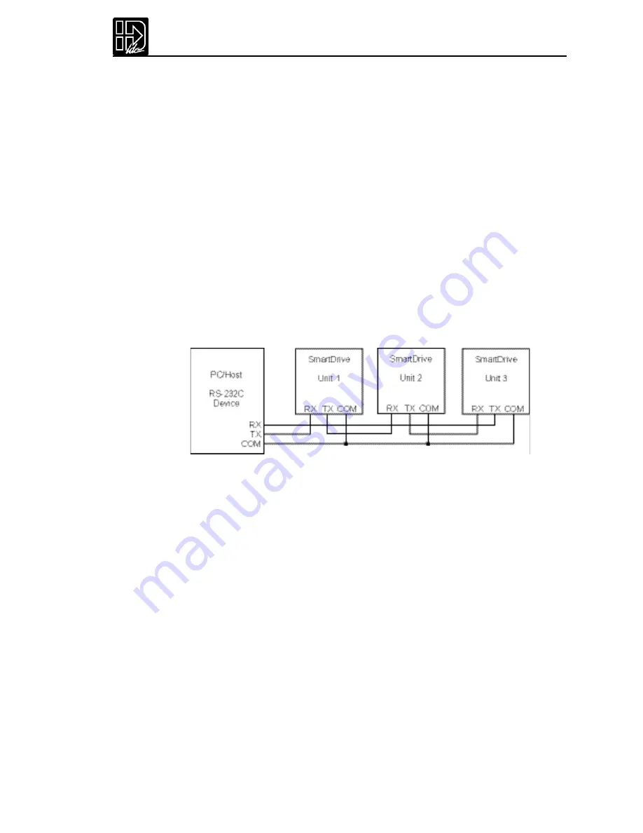
Rules for Daisy Chain Operation
1.
Units on a daisy chain must be “device addressed’(numbered) in ascending
order away from the host device/controller in order for the Load All (LA - EX)
commands to work properly.The unit addresses are not required to be numeri-
cally sequential,but must be in ascending order.
Example:1,2,4,6,8 is valid addressing. 6,3,10,8,2 is not valid.
2.
Do not duplicate unit numbers or addresses.
3.
RS-232C Echo should be enabled for each unit on the daisy chain.Disabling RS-
232C Echo will prevent the daisy chain from functioning properly.
4.
Any loose RS-232C connections or miswiring along the daisy chain will cause
communication to fail.Please double check wiring if communication problems
arise.
5.
“Device Addressing”RS-232C commands (using the specific unit number in
front of the command) is necessary if the user wants only one specific unit to
perform an operation.
6.
Status commands require addressing.
Please call IDC if you need to daisy chain more than 99 drives.
The hardware configuration below shows how to connect the daisy chain.
Section 2: Application Developer Software
All of IDC’s SmartDrives come with
Application De veloper
software.The programs
and data files are automatically installed with a setup utility included on the disk.
Installing Application Developer in Windows 95, 98, or NT
1.
Insert
Application De veloper
CD-Rom in your CD-Rom drive.
2.
Click on Start.
3.
Click on Run.
4.
If there is no drive specified in the Command Line box,type the drive letter,
followed by a colon (:),then a backslash (\),and the word
setup
.
For example:
d:\software\Application Developer\setup
5.
Click OK.
The installation program will display the Welcome screen shown below.
Throughout the installation process,the program will prompt you to enter informa-
tion.Click on the
Next
button to continue the installation.At any point during the
installation, you can click on
Cancel
to abort the process.
The Setup program will take you through a series of screens to verify user informa-
tion and destination directories.
Summary of Contents for B8961
Page 111: ...109 Chapter 7 Programming with Serial Communication...
Page 132: ...B8961 and B8962 User Manual 130...
Page 136: ...B8961 and B8962 User Manual 134 B8961 and B8962 Hardware Connections...
Page 137: ...135 Chapter 8 Hardware Reference B8961 and B8962 Input and Output Schematics...
Page 138: ...B8961 and B8962 User Manual 136 Connecting IDC Limit Switches to the B8961 2...
Page 156: ...B8961 and B8962 User Manual 154...


