B8961 and B8962 User Manual
24
MECH Mechanical Configuration
Through the mechanical setup menu, your
IDeal
™
Programmable Smart Drive
allows you to program in distance, velocity and acceleration units con venient for
your application.Once configured, your keypad will use these units in all display
and position reporting modes.This menu also allows you to compensate for a
known amount of backlash in your mechanical system,and to set a maximum
allowable speed for each axis.
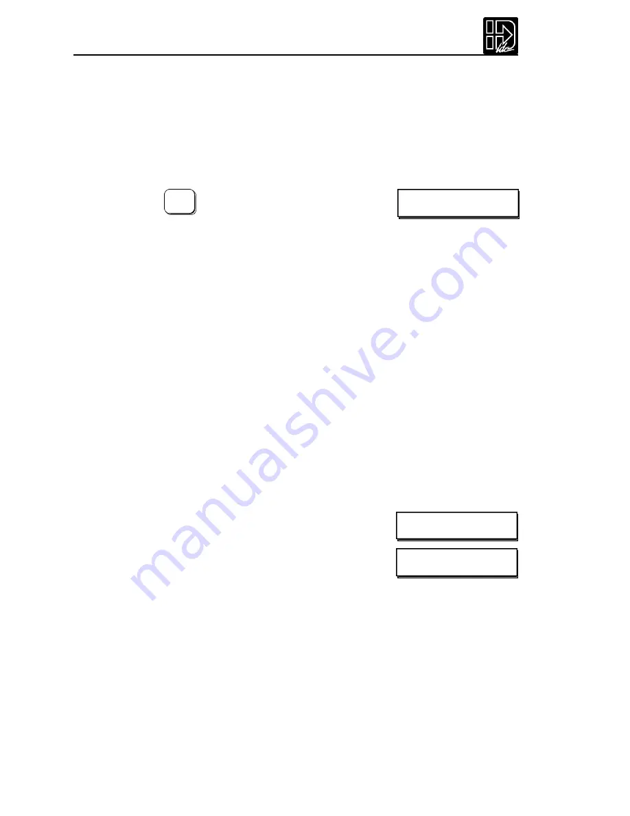
Pressing the MECH function k ey displays three menu
choices:
Pressing
â
reveals three additional menu choices:
--
á
MECH SETUP
â
--
DIST RATIO BKLASH
--
á
MECH SETUP
â
--
VEL VMAX ACCEL
Specifying the wrong encoder resolution will prevent the Smart Drive from
properly communicating the motor and could damage it,as well as cause unstable
system behavior. For this reason,IDC fixes the encoder resolution for our servo
motors.Consult the factory if your application requires using another motor or
resolution encoder.
1.
Use
ß
and
à
keys to select an axis.
2.
Use the
áâ
and ENTER keys to select from a list of encoder resolutions,or
use the numeric k eys to enter the encoder resolution.
This option defines the maximum position following error allowed during motion.
A fault occurs when the error between the commanded and feedback signal
exceeds the Following Er ror value.
Range:0-524,000 step counts,0 = OFF
If a Following - Error occurs,the control will enter a fault state where:
• Any motion or program being executed is immediately terminated.
• The LCD Display will indicate “Following Error”,along with an explanation.
• A fault output will be generated if defined as a “Stall”or Fault output.
• The ESC key or a RESET (either an input or via RS-232) will need to be issued
before motion can occur.
EDIT
SETUP ENC FOL-ERR
Following Error Limit [FE]
Default:8,000 counts
- - Axis One Fol Error - -
ß
8000 steps
à
Summary of Contents for B8961
Page 111: ...109 Chapter 7 Programming with Serial Communication...
Page 132: ...B8961 and B8962 User Manual 130...
Page 136: ...B8961 and B8962 User Manual 134 B8961 and B8962 Hardware Connections...
Page 137: ...135 Chapter 8 Hardware Reference B8961 and B8962 Input and Output Schematics...
Page 138: ...B8961 and B8962 User Manual 136 Connecting IDC Limit Switches to the B8961 2...
Page 156: ...B8961 and B8962 User Manual 154...


