64
ON
O
FF
S1
R
S
48
5+
R
S
48
5-
GN
D
R
S
485
1
R
S
485
2
ON
O
FF
S1
R
S
48
5+
R
S
48
5-
GN
D
R
S
485
1
1
2
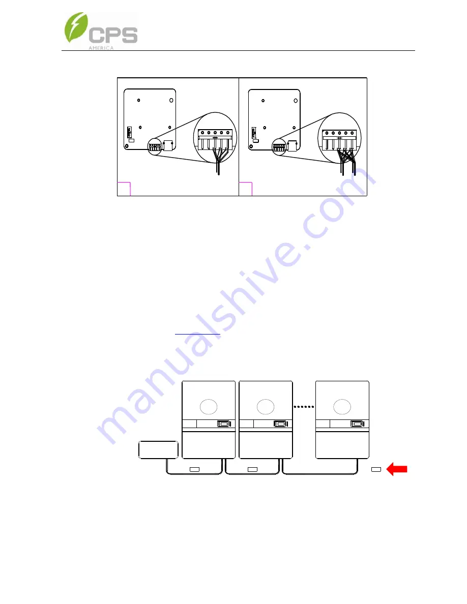
Figure 3-41 RS485 Connection of Standard wirebox
3.4.3. RS485 Network Set-up
When the inverters are monitored via the RS485 communication, a unique RS485
address for each inverter can be set up through the LCD interface. Up to 32 inverters
can be connected in the RS485 communication network. The daisy-chain topology is
recommended for the RS485 network connection to minimize noise and bus
reflections, as shown in
Figure 3-42
. Other communication topologies, such as the
star networks, are not recommended. All RS485 connections must be terminated
in a serial fashion and not to exceed 32 in total.
1
2
N
Datalogger
OFF
S402
OFF
S402
ON
S402
Figure 3-42 RS485 Network Connection
Summary of Contents for SCA50KTL-DO/US-480
Page 2: ......
Page 6: ......
Page 53: ...47 Figure 3 24 Bypass Terminal option installed within the Standard wirebox ...
Page 139: ...133 Figure 10 1 CPS SCA50KTL kW and kVA derating curves of PV input voltage ...
Page 140: ...134 Figure 10 2 CPS SCA60KTL kW and kVA derating curves of PV input voltage ...
Page 141: ...135 Figure 10 2 CPS SCA60KTL Reactive Power Capability ...


