Contents
Contents
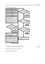
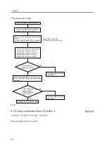
2.1.1 Image Adjustment Basic Procedure 1 ......................................................................................................... 2-1
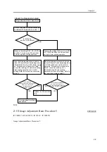
2.1.2 Image Adjustment Basic Procedure 2 ......................................................................................................... 2-2
2.1.3 Image Adjustment Basic Procedure 3 ......................................................................................................... 2-3
2.1.4 Image Adjustment Basic Procedure 4 ......................................................................................................... 2-4
2.1.5 Image Adjustment Basic Procedure 5 ......................................................................................................... 2-5
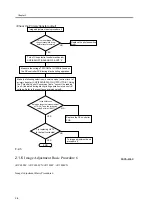
2.1.6 Image Adjustment Basic Procedure 6 ......................................................................................................... 2-6
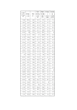
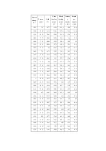
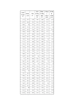
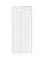
2.1.7 Potential Control Conversion Table ............................................................................................................ 2-7
2.2.1 Image Position ........................................................................................................................................... 2-18
2.2.2 Checking the Image Position..................................................................................................................... 2-19
2.2.3 Cassette...................................................................................................................................................... 2-20
2.2.4 Manual Feed Tray ..................................................................................................................................... 2-21
2.2.5 Front Deck ................................................................................................................................................. 2-22
2.5.1 After Replacing the Black Developing Unit ............................................................................................. 2-31
2.5.2 Points to Note When Mounting the Polarity Positioning Plate ................................................................. 2-31
2.5.3 Replacing the Color Developing Unit ....................................................................................................... 2-32
2.5.4 Replacing the Starter of the Color Developing Unit ................................................................................. 2-36
2.5.5 After Replacing the Primary Charging Assembly..................................................................................... 2-39
2.5.6 After Replacing the Primary Charging Wire............................................................................................. 2-40
2.5.7 After Replacing the Pre-Transfer Charging Wire ..................................................................................... 2-40
2.5.8 After Replacing the Pre-Transfer Charging Wire ..................................................................................... 2-40
2.5.9 After Replacing the Waste Toner Box ...................................................................................................... 2-40
2.5.10 After Replacing the ITB Cleaning Blade ................................................................................................ 2-40
2.5.11 After Repacking the Photosensitive Drum Cleaning Blade .................................................................... 2-44
2.5.12 Replacing the Photosensitive Drum ........................................................................................................ 2-45
2.5.13 Points to Note When Replacing the Drum Heater .................................................................................. 2-46
2.5.14 Points to Note When Replacing the Drum Heater PCB .......................................................................... 2-48
2.5.15 After Repacking the ITB ........................................................................................................................ 2-50
2.5.16 After Replacing the Primary Transfer Roller .......................................................................................... 2-50
2.6.1 Points to Note When Mounting the Fixing Assembly .............................................................................. 2-54
2.6.2 After Replacing the Fixing Roller ............................................................................................................. 2-54
2.6.3 After Replacing the Fixing Web ............................................................................................................... 2-54
2.6.4 Position of the Fixing inlet Guide ............................................................................................................. 2-54
2.6.5 Points to Note When Mounting the Pressure Roller ................................................................................. 2-55
2.6.6 Adjusting the Nip Pressure of the Pressure Roller ................................................................................... 2-55
Summary of Contents for iR C6800 Series
Page 1: ...Jan 20 2005 Portable Manual iR C6800 Series ...
Page 2: ......
Page 6: ......
Page 12: ......
Page 13: ...Chapter 1 Maintenance and Inspection ...
Page 14: ......
Page 16: ......
Page 20: ...Chapter 1 1 4 Under high humidity and high temperature condition 85 000 images ...
Page 51: ...Chapter 2 Standards and Adjustments ...
Page 52: ......
Page 79: ...F 2 27 1 ...
Page 99: ...F 2 88 F 2 89 1 OK NG NG ...
Page 110: ......
Page 111: ...Chapter 3 Error Code ...
Page 112: ......
Page 114: ......
Page 172: ......
Page 173: ...Chapter 4 User Mode Items ...
Page 174: ......
Page 176: ......
Page 188: ...LIPS emulation 12 items utility printer initialize yes no Item Description ...
Page 190: ......
Page 191: ...Chapter 5 Service Mode ...
Page 192: ......
Page 380: ......
Page 381: ...Chapter 6 Outline of Components ...
Page 382: ......
Page 384: ......
Page 387: ...F 6 1 SL7 CL3 CL2 SL6 SL8 SL9 SL2 SL1 SL4 SL3 SL5 CL1 SL10 SL11 SL12 ...
Page 397: ...F 6 5 FM2 FM10 FM11 FM12 FM6 FM3 FM4 FM8 FM9 FM5 FM7 FM1 ...
Page 407: ...F 6 9 PS65 PS38 PS39 PS46 PS44 PS45 PS52 PS53 PS58 PS59 PS37 ...
Page 417: ...F 6 13 13 2 5 3 14 15 16 9 6 12 7 1 11 4 25 24 21 23 19 20 31 29 28 27 26 22 18 17 32 30 10 8 ...
Page 418: ......
Page 419: ...Chapter 7 System Construction ...
Page 420: ......
Page 422: ......
Page 443: ...Chapter 8 Upgrading ...
Page 444: ......
Page 446: ......
Page 455: ...Jan 20 2005 ...
Page 456: ......


