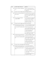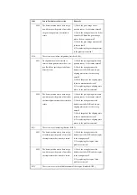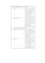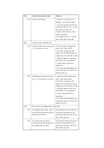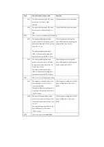
xxDB
For INIT control (service mode
INISET-*) at time of initial setup, the
variation among the 72 light Ref
samplings is 100 or more.
The ATR sensor is damaged or has an
open circuit. The connector has poor
contact.
Turn off and then on the main power;
then, execute the intermediate transfer
belt.
xxDC
For INIT control (service mode
INISET-*), the average of the patch Sig
values is 800 or higher.
The patch sensor is damaged or has an
open circuit. The connector has poor
contact. the primary transfer
engagement if faulty. The mounting of
the developing assembly is faulty. The
amount of supply is too high.
Turn off and then on the main power;
then, execute the intermediate transfer
belt.
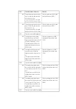
xxF1
The connector or the color toner supply
clutch is not connected.
Turn off and then on the main power;
then, execute ITB cleaning.
xxFF
There is no toner inside the Bk
developing assembly.
- the toner is not supplied to the
developing assembly correctly.
- the hopper stirring motor is not
rotating normally.
The hopper connector has poor contact.
The black toner supply motor (M25) is
faulty. The hopper stirring motor (M23)
is faulty. The black toner level sensor is
faulty. The DC controller is faulty.
Turn off and then on the main power;
then, execute the intermediate transfer
belt.
E021
There is an error in the rotation of the developing assembly.
0001
The developing rotary home position is
not detected.
The motor rotates out of sync because
of poor torque caused by any of the
following: The developing rotary HP
sensor is faulty; the wiring of the DC
controller is faulty; there is an excess
load on the developing assembly.
Turn off and then on the main power.
Code
Cause/Particulars of detection
Remarks
Summary of Contents for iR C6800 Series
Page 1: ...Jan 20 2005 Portable Manual iR C6800 Series ...
Page 2: ......
Page 6: ......
Page 12: ......
Page 13: ...Chapter 1 Maintenance and Inspection ...
Page 14: ......
Page 16: ......
Page 20: ...Chapter 1 1 4 Under high humidity and high temperature condition 85 000 images ...
Page 51: ...Chapter 2 Standards and Adjustments ...
Page 52: ......
Page 79: ...F 2 27 1 ...
Page 99: ...F 2 88 F 2 89 1 OK NG NG ...
Page 110: ......
Page 111: ...Chapter 3 Error Code ...
Page 112: ......
Page 114: ......
Page 172: ......
Page 173: ...Chapter 4 User Mode Items ...
Page 174: ......
Page 176: ......
Page 188: ...LIPS emulation 12 items utility printer initialize yes no Item Description ...
Page 190: ......
Page 191: ...Chapter 5 Service Mode ...
Page 192: ......
Page 380: ......
Page 381: ...Chapter 6 Outline of Components ...
Page 382: ......
Page 384: ......
Page 387: ...F 6 1 SL7 CL3 CL2 SL6 SL8 SL9 SL2 SL1 SL4 SL3 SL5 CL1 SL10 SL11 SL12 ...
Page 397: ...F 6 5 FM2 FM10 FM11 FM12 FM6 FM3 FM4 FM8 FM9 FM5 FM7 FM1 ...
Page 407: ...F 6 9 PS65 PS38 PS39 PS46 PS44 PS45 PS52 PS53 PS58 PS59 PS37 ...
Page 417: ...F 6 13 13 2 5 3 14 15 16 9 6 12 7 1 11 4 25 24 21 23 19 20 31 29 28 27 26 22 18 17 32 30 10 8 ...
Page 418: ......
Page 419: ...Chapter 7 System Construction ...
Page 420: ......
Page 422: ......
Page 443: ...Chapter 8 Upgrading ...
Page 444: ......
Page 446: ......
Page 455: ...Jan 20 2005 ...
Page 456: ......


