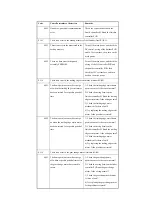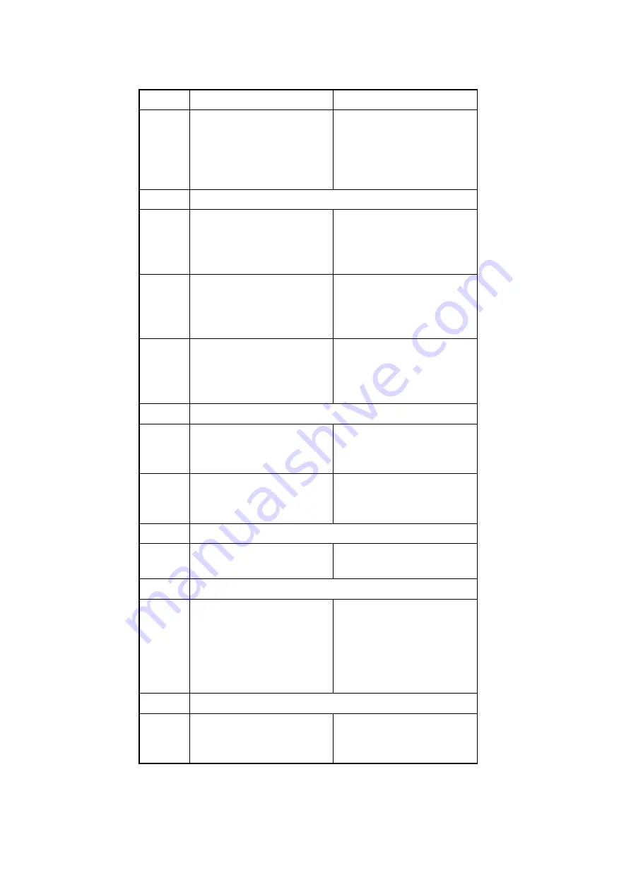
0000
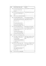
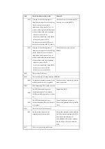
At start-up, there is an error in the
communication between main
controller PCB (sub) and the main
controller PCB (main).
Turn off the main power, and replace
the main controller PCB (sub).
If the result is not good, replace the
main controller PCB (main), and turn
on the main power.
E400
There is a DF communication error.
0001
There is a check sum error.
Disconnect and connect the harness
connector; then, replace the reader
controller PCB or the ADF DC
controller.
0002
There is a reception status error.
Disconnect and connect the harness
connector; then, replace the reader
controller PCB or the ADF DC
controller.
0003
There is a reception interrupt error.
Disconnect and connect the harness
connector; then, replace the reader
controller PCB or the ADF DC
controller.
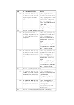
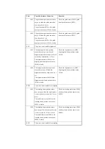
E413
There is an error in the DF shift motor.
0001
The shift HP sensor is open.
Check the harness; then, as necessary,
replace the sensor and motor. Check the
mounting of the parts around the cam.
0002
The shift HP sensor is closed.
Check the harness; then, as necessary,
replace the sensor and motor. Check the
mounting of the parts around the cam.
E490
The DF is of the wrong model.
0001
The installed DF is not of the correct
type.
Replace the DF with one of an
appropriate type.
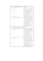
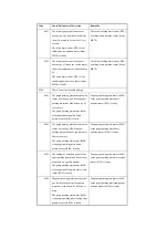
E500
There is a finisher communication error.
0001
There is an error in data
communication.
An error has been detected in terms of
the number of errors or the duration of
the error in the communication between
copier and finisher.
Turn off the main power, and check the
DC controller, wiring of the finisher
PCB, and 24V system fuse; then, turn
on the main power.
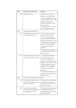
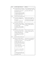
E503
There is an error in the communication within the finisher (finisher R1/R2).
0002
There is a data communication error.
finisher-to-saddle unit communication
error
Check the connection between the
saddle stitcher controller PCB and the
finisher controller PCB.
Code
Cause/Particulars of detection
Remarks
Summary of Contents for iR C6800 Series
Page 1: ...Jan 20 2005 Portable Manual iR C6800 Series ...
Page 2: ......
Page 6: ......
Page 12: ......
Page 13: ...Chapter 1 Maintenance and Inspection ...
Page 14: ......
Page 16: ......
Page 20: ...Chapter 1 1 4 Under high humidity and high temperature condition 85 000 images ...
Page 51: ...Chapter 2 Standards and Adjustments ...
Page 52: ......
Page 79: ...F 2 27 1 ...
Page 99: ...F 2 88 F 2 89 1 OK NG NG ...
Page 110: ......
Page 111: ...Chapter 3 Error Code ...
Page 112: ......
Page 114: ......
Page 172: ......
Page 173: ...Chapter 4 User Mode Items ...
Page 174: ......
Page 176: ......
Page 188: ...LIPS emulation 12 items utility printer initialize yes no Item Description ...
Page 190: ......
Page 191: ...Chapter 5 Service Mode ...
Page 192: ......
Page 380: ......
Page 381: ...Chapter 6 Outline of Components ...
Page 382: ......
Page 384: ......
Page 387: ...F 6 1 SL7 CL3 CL2 SL6 SL8 SL9 SL2 SL1 SL4 SL3 SL5 CL1 SL10 SL11 SL12 ...
Page 397: ...F 6 5 FM2 FM10 FM11 FM12 FM6 FM3 FM4 FM8 FM9 FM5 FM7 FM1 ...
Page 407: ...F 6 9 PS65 PS38 PS39 PS46 PS44 PS45 PS52 PS53 PS58 PS59 PS37 ...
Page 417: ...F 6 13 13 2 5 3 14 15 16 9 6 12 7 1 11 4 25 24 21 23 19 20 31 29 28 27 26 22 18 17 32 30 10 8 ...
Page 418: ......
Page 419: ...Chapter 7 System Construction ...
Page 420: ......
Page 422: ......
Page 443: ...Chapter 8 Upgrading ...
Page 444: ......
Page 446: ......
Page 455: ...Jan 20 2005 ...
Page 456: ......


