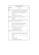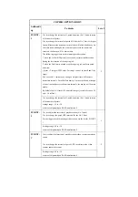
SVMD-
ENT
Switching the method of entering the Service Mode.
2
Setting Values
0: [User Mode key] -> Press [2] and [8] simultaneously -> [User Mode
key]
[Initial setting upon shipment/value after RAM clear]
1: [User Mode key] -> Press [4] and [9] simultaneously -> [User Mode
key]
Reference Information
Support for Siemens
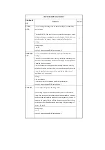
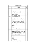
DH-
MODE
Patch Data (high density side) Used in D-half Except in Full Correction
Change the default setting so that the readout collected from D-half at
time of full correction will be substituted for the patch on the high
density side at time of D-half (other than in full correction).
2
Settings
0: use patch image read data of full correction (at time of shipment/upon
RAM initialization)
1: do not use patch image read data of full correction
at time of shipment/upon RAM initialization: 0
W-CLN-
PH
Use it to set the intervals at which the primary charging wire/pre-transfer
charging wire is automatically cleaned.
If an image fault (e.g., vertical lines) occurs in a high temperature/
humidity environment, the intervals at which the primary charging wire/
pre-transfer charging wire is automatically cleaned may be changed.
Note: In a normal environment, be sure to use W-CLN-P to set the
intervals used to automatically clean the primary charging wire.
2
Range of settings
100 to 1000
at time of shipment/upon RAM initialization: 1000
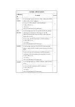
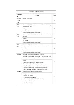
B-SPL-
SW
Use it to set the environment table for black toner supply.
2
settings range
0: variable
1: fixed
at time of shipment/upon RAM initialization: 0
B-CNT-
SW
Use it to set the environment table for black development contrast.
2
settings range
0: variable
1: fixed
at time of shipment/upon RAM initialization: 0
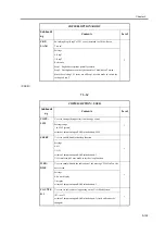
COPIER>OPTION>BODY
Subheadi
ng
Contents
Level
Summary of Contents for iR C6800 Series
Page 1: ...Jan 20 2005 Portable Manual iR C6800 Series ...
Page 2: ......
Page 6: ......
Page 12: ......
Page 13: ...Chapter 1 Maintenance and Inspection ...
Page 14: ......
Page 16: ......
Page 20: ...Chapter 1 1 4 Under high humidity and high temperature condition 85 000 images ...
Page 51: ...Chapter 2 Standards and Adjustments ...
Page 52: ......
Page 79: ...F 2 27 1 ...
Page 99: ...F 2 88 F 2 89 1 OK NG NG ...
Page 110: ......
Page 111: ...Chapter 3 Error Code ...
Page 112: ......
Page 114: ......
Page 172: ......
Page 173: ...Chapter 4 User Mode Items ...
Page 174: ......
Page 176: ......
Page 188: ...LIPS emulation 12 items utility printer initialize yes no Item Description ...
Page 190: ......
Page 191: ...Chapter 5 Service Mode ...
Page 192: ......
Page 380: ......
Page 381: ...Chapter 6 Outline of Components ...
Page 382: ......
Page 384: ......
Page 387: ...F 6 1 SL7 CL3 CL2 SL6 SL8 SL9 SL2 SL1 SL4 SL3 SL5 CL1 SL10 SL11 SL12 ...
Page 397: ...F 6 5 FM2 FM10 FM11 FM12 FM6 FM3 FM4 FM8 FM9 FM5 FM7 FM1 ...
Page 407: ...F 6 9 PS65 PS38 PS39 PS46 PS44 PS45 PS52 PS53 PS58 PS59 PS37 ...
Page 417: ...F 6 13 13 2 5 3 14 15 16 9 6 12 7 1 11 4 25 24 21 23 19 20 31 29 28 27 26 22 18 17 32 30 10 8 ...
Page 418: ......
Page 419: ...Chapter 7 System Construction ...
Page 420: ......
Page 422: ......
Page 443: ...Chapter 8 Upgrading ...
Page 444: ......
Page 446: ......
Page 455: ...Jan 20 2005 ...
Page 456: ......


