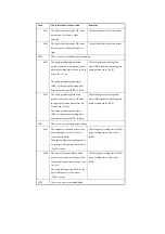
0003
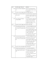
The logical motor position differs
between before and after the detection
operation.
Turn off and then on the main power.
E061
At time of potential control, a specific level of potential is absent. Or, the limiter
goes on.
0001
When forming an image, the potential
is 10 V or less during initial rotation.
Turn off and then on the main power.
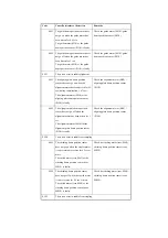
0002
At time of potential control, the
potential is 10 V or less during initial
rotation.
Turn off and then on the main power.
0003
While the grid bias is being adjusted, a
level of potential higher than the grid
bias is sampled.
Turn off and then on the main power.
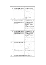
0005
The difference in potential between
dark and light areas is less than 100 V.
Turn off and then on the main power.
0007
During adjustment of EPC offset, the
potential that is read is outside the +/-30
V range.
Turn off and then on the main power.
0008
During dark area potential adjustment,
the sampling value is too low.
Turn off and then on the main power.
0010
The sampling of the light area potential
is faulty.
Turn off and then on the main power.
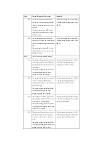
E070
There is an error in the detection of the ITB home position.
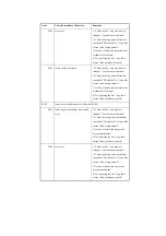
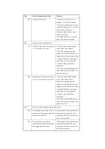
xx=01: HP1, xx=02: HP2; only at ITB 1/1 speed; XX=00: no distinction
00xx
The home position of the intermediate
transfer belt is not detected within a
specific period of time .
The ITB HP sensor is faulty.
Turn off the main power, and check the
DC controller PCB and the ITB HP
sensor; then, turn on the main power.
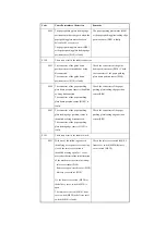
01xx
The period of time between when the
home position of the intermediate
transfer belt is detected and the next
home position is detected is longer than
specified .
The presence of a tear may have caused
the sensor to wrongly identify it as
indicating the home position.
Turn off the main power, and check the
drive of the intermediate transfer belt;
then, turn on the main power.
Code
Cause/Particulars of detection
Remarks
Summary of Contents for iR C6800 Series
Page 1: ...Jan 20 2005 Portable Manual iR C6800 Series ...
Page 2: ......
Page 6: ......
Page 12: ......
Page 13: ...Chapter 1 Maintenance and Inspection ...
Page 14: ......
Page 16: ......
Page 20: ...Chapter 1 1 4 Under high humidity and high temperature condition 85 000 images ...
Page 51: ...Chapter 2 Standards and Adjustments ...
Page 52: ......
Page 79: ...F 2 27 1 ...
Page 99: ...F 2 88 F 2 89 1 OK NG NG ...
Page 110: ......
Page 111: ...Chapter 3 Error Code ...
Page 112: ......
Page 114: ......
Page 172: ......
Page 173: ...Chapter 4 User Mode Items ...
Page 174: ......
Page 176: ......
Page 188: ...LIPS emulation 12 items utility printer initialize yes no Item Description ...
Page 190: ......
Page 191: ...Chapter 5 Service Mode ...
Page 192: ......
Page 380: ......
Page 381: ...Chapter 6 Outline of Components ...
Page 382: ......
Page 384: ......
Page 387: ...F 6 1 SL7 CL3 CL2 SL6 SL8 SL9 SL2 SL1 SL4 SL3 SL5 CL1 SL10 SL11 SL12 ...
Page 397: ...F 6 5 FM2 FM10 FM11 FM12 FM6 FM3 FM4 FM8 FM9 FM5 FM7 FM1 ...
Page 407: ...F 6 9 PS65 PS38 PS39 PS46 PS44 PS45 PS52 PS53 PS58 PS59 PS37 ...
Page 417: ...F 6 13 13 2 5 3 14 15 16 9 6 12 7 1 11 4 25 24 21 23 19 20 31 29 28 27 26 22 18 17 32 30 10 8 ...
Page 418: ......
Page 419: ...Chapter 7 System Construction ...
Page 420: ......
Page 422: ......
Page 443: ...Chapter 8 Upgrading ...
Page 444: ......
Page 446: ......
Page 455: ...Jan 20 2005 ...
Page 456: ......


