background image

Chapter 1

1-29

F-1-11

3: Do not shift the drum phase as part of normal work involving drawing out of the process unit.
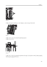
2-8 After fitting the drum fixing member [2] to the drum flange [1], hold it down from above using the drum stop
tool [3]. Thereafter, tighten the drum fixing screw [4] with a screwdriver.
Be sure to fix the protrusion [5] of the drum stop tool in place with a screw after matching it
against the cut-off [6] of the drum flange.

F-1-12

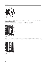
2-9 After checking the drum phase position, put a check mark on the drum phase label [1] attached behind the process

[A]

Position of the Flange Before the 
Phase Is Shifted (at time of shipment)

Position of the Flange After the 
Phase Is Shifted (after the shift 
work for the first time)

[6]

[3]

[4]

[5]

[2]

[1]

Summary of Contents for iR C6800 Series

Page 1: ...Jan 20 2005 Portable Manual iR C6800 Series ...

Page 2: ......

Page 3: ... need arises In the event of major changes in the contents of this manual over a long or short period Canon will issue a new edition of this manual The following paragraph does not apply to any countries where such provisions are inconsistent with local law Trademarks The product names and company names used in this manual are the registered trademarks of the individual companies Copyright This ma...

Page 4: ...quiring care to avoid combustion fire Indicates an item prohibiting disassembly to avoid electric shocks or problems Indicates an item requiring disconnection of the power plug from the electric outlet Indicates an item intended to provide notes assisting the understanding of the topic in question Indicates an item of reference assisting the understanding of the topic in question Provides a descri...

Page 5: ...sed to indicate Low The voltage value however differs from circuit to circuit In addition the asterisk as in DRMD indicates that the DRMD signal goes on when 0 In practically all cases the internal mechanisms of a microprocessor cannot be checked in the field Therefore the operations of the microprocessors used in the machines are not discussed they are explained in terms of from sensors to the in...

Page 6: ......

Page 7: ...stration Guide and Transparency Sensor 1 32 Chapter 2 Standards and Adjustments 2 1 Image Adjustment Basic Procedure 2 1 2 1 1Image Adjustment Basic Procedure 1 2 1 2 1 2Image Adjustment Basic Procedure 2 2 2 2 1 3Image Adjustment Basic Procedure 3 2 3 2 1 4Image Adjustment Basic Procedure 4 2 4 2 1 5Image Adjustment Basic Procedure 5 2 5 2 1 6Image Adjustment Basic Procedure 6 2 6 2 1 7Potential ...

Page 8: ...e Pressure Roller 2 42 2 6 6Adjusting the Nip Pressure of the Pressure Roller 2 42 2 6 7Adjusting the Position of the Feeding Web Solenoid SL2 2 42 2 6 8Points to Note About the Position of the Fixing Thermal Switch 2 42 2 6 9Points to Note When Mounting the Shift Thermal Switch 2 43 2 6 10Points to Note When Mounting the Outside Heating Roller Thermal Switch 2 43 2 6 11Points to Note When Mountin...

Page 9: ...1Overview 5 1 5 1 2Test Print TYPE 5 1 5 1 3Selecting Test Print TYPE 5 1 5 1 416 Gradation TYPE 4 5 2 5 1 5Full Page Halftone TYPE 5 5 2 5 1 6Grid TYPE 6 5 3 5 1 7MCYBk Horizontal Stripes TYPE 10 5 4 5 1 864 Gradation TYPE 12 5 5 5 1 9Full Color 16 Gradation TYPE 14 5 5 5 2 DISPLAY Status Display Mode 5 7 5 2 1 COPIER 5 7 5 2 1 1 COPIER List 5 7 5 2 2 FEEDER 5 24 5 2 2 1 FEEDER List 5 24 5 3 I O ...

Page 10: ...170 Chapter 6 Outline of Components 6 1 Clutch Solenoid 6 1 6 1 1Clutches and Solenoids 6 1 6 2 Motor 6 4 6 2 1Motors 6 4 6 3 Fan 6 10 6 3 1Fans 6 10 6 4 Sensor 6 14 6 4 1Sensors 6 14 6 5 Switch 6 24 6 5 1Switches 6 24 6 6 Lamps Heaters and Others 6 26 6 6 1Heaters Lamps and Others 6 26 6 7 PCBs 6 30 6 7 1PCB 6 30 Chapter 7 System Construction 7 1 Construction 7 1 7 1 1Functional Construction 7 1 ...

Page 11: ... 13 7 4 1Print Speed 7 13 7 4 2Print Speed 7 15 7 4 3Paper Type 7 18 7 4 4Accessories 7 19 Chapter 8 Upgrading 8 1 Outline of the Version Upgrade 8 1 8 2 Outline of the Service Support Tool 8 2 8 3 Network Interface of the Machine with the SST in Use 8 5 ...

Page 12: ......

Page 13: ...Chapter 1 Maintenance and Inspection ...

Page 14: ......

Page 15: ... Unit 1 5 1 2 4 Printer Unit 1 5 1 2 5 Printer Unit 1 10 1 3 Scheduled Servicing Basic Procedure 1 14 1 3 1 Scheduled Servicing Basic Procedure 1 14 1 3 2 Scheduled Servicing reader unit 1 15 1 3 3 Scheduled Servicing printer unit 1 16 1 3 4 Shifting the Photosensitive Drum Phase 1 24 1 4 Cleaning 1 32 1 4 1 Cleaning the Secondary Transfer Rear Guide 1 32 1 4 2 Cleaning the Registration Roller Reg...

Page 16: ......

Page 17: ... indicated may vary depending on the site environment and user habit Checking the Timing of Replacement The timing of replacement may be checked using the following service mode items Copier COPIER COUNTER PRDC 1 Accessory COPIER COUNTER PRDC 2 1 1 2 Reader Unit 0000 9633 iR C6800C iR C6800CN iR 5800C iR 5800CN The machine s reader unit does not have parts that must be replaced on a periodical bas...

Page 18: ...images 8 Pre transfer charging assembly wire cleaner 2 FL2 2428 000 1 500 000 images 9 Primary grid wire FY1 0883 000 1 500 000 images 10 Fixing thermistor FK2 0013 000 1 500 000 prints 11 Pressure thermistor FK2 0013 000 1 500 000 prints 12 Outside heating roller thermistor FK2 0013 000 1 500 000 prints 13 Primary charging assembly FM2 0429 000 1 1 000 000 images 14 Pre transfer charging assembly...

Page 19: ... 000 images 7 Pre transfer charging assembly wire cleaner 1 FL2 2427 000 1 500 000 images 8 Pre transfer charging assembly wire cleaner 2 FL2 2428 000 1 500 000 images 9 Primary grid wire FY1 0883 000 1 500 000 images 10 Fixing thermistor FK2 0013 000 1 500 000 prints 11 Pressure thermistor FK2 0013 000 1 500 000 prints 12 Outside heating roller thermistor FK2 0013 000 1 500 000 prints 13 Primary ...

Page 20: ...Chapter 1 1 4 Under high humidity and high temperature condition 85 000 images ...

Page 21: ... COUNTER DRBL 2 1 2 2 Overview 0005 8049 iR C6800C iR C6800CN iR 5800C iR 5800CN Some parts of the machine may have to be replaced once or more over the period of machine warranty because of wear or damage Replace them as needed by referring to the table of estimated lives expressed in terms of the number of prints they make Making Checks When Replacing Durables Use the following service mode item...

Page 22: ...1 150 000 prints 6 Pressure roller FC5 6299 000 1 150 000 prints 7 Outside heating roller FC5 2285 000 1 150 000 prints 8 ITB cleaner blade FC5 1662 000 1 195 000 images 2 lubricate fluorine graghite 9 Secondary transfer outside roller FC5 2157 000 1 195 000 images 2 10 Primary transfer roller FC5 1660 000 1 165 000 images 2 11 Cleaner blade FC5 1788 000 1 195 000 images 2 one edge in use lubricat...

Page 23: ...ller FC5 1661 000 1 300 000 prints 21 Cleaner scoop up sheet FL2 0422 000 1 390 000 images 2 22 Edge scraper FC5 5136 000 2 500 000 images 2 23 Color developing assembly FM2 0446 000 3 500 000 prints 24 Fixing web FC5 2286 000 1 500 000 prints 25 Fixing heat insulating bush FB5 3613 000 2 500 000 prints 26 Delivery upper separation claw FM2 1672 000 4 500 000 prints 27 Delivery lower separation cl...

Page 24: ...es 2 33 Bk developing cylinder black developing assembly FM2 0434 000 1 1 000 000 prints 34 Developing roll black developing assembly FC5 1863 000 2 1 000 000 prints 2004 年 10 月現在 番号 部品名称 部品番号 数 量 交換目安 備考 1 搬送ローラ 手差し FB1 8581 000 1 12 万枚 2 分離ローラ 手差し FB5 0873 000 1 12 万枚 3 ITB クリーナすくいシー ト FL2 0411 000 1 15 万枚 4 二次転写除電針 FL2 0598 000 1 15 万枚 5 定着ローラ FC5 6298 000 1 15 万枚 1 6 加圧ローラ FC5 6299 000 1 15 万枚...

Page 25: ...0 各 1 25 万枚 16 搬送ローラ カセット 3 4 FC5 2526 000 各 1 25 万枚 17 分離ローラ カセット 3 4 FC5 2528 000 各 1 25 万枚 18 一次転写除電針 FM2 0420 000 1 30 万イメー ジ 2 19 ITB FC5 1658 000 1 30 万イメー ジ 2 20 二次転写内ローラ FC5 1661 000 1 30 万枚 21 クリーナすくいシート FL2 0422 000 1 39 万イメー ジ 22 端部スクレーパ FC5 5136 000 2 50 万イメー ジ 2 23 カラー現像ユニット FM2 0446 000 3 50 万枚 24 定着ウェブ FC5 2286 000 1 50 万枚 25 定着断熱ブッシュ FB5 3613 000 2 50 万枚 26 排紙上分離爪 FM2 1672 000 4 50...

Page 26: ...圧断熱ブッシュ RB1 0325 000 2 50 万枚 29 外部加熱断熱ブッシュ FC5 2582 000 2 50 万枚 30 ITB 端部スクレーパ FC6 2843 000 2 60 万イメー ジ 31 オゾンフィルタ 定着排 熱ファン FC5 6370 000 1 100 万イメー ジ 32 トナーフィルタ 機内 FL2 0554 000 1 100 万イメー ジ 33 Bk 現像シリンダ 黒現像 器 FM2 0434 000 1 100 万枚 34 現像コロ 黒現像器 FC5 1863 000 2 100 万枚 as of March 2004 Ref Parts name Parts No Q t y Interval Remarks 1 Feed roller manual feed FB1 8581 000 1 120 000 prints 2 Separation r...

Page 27: ...C5 2157 000 1 195 000 images 2 10 Primary transfer roller FC5 1660 000 1 195 000 images 2 11 Cleaner blade FC5 1788 000 1 195 000 images 2 one edge in use lubricate fluorine graghite 12 Pickup roller left right paper deck FC5 2524 000 1 eac h 250 000 prints 13 Feed roller left right paper deck FC5 2526 000 1 eac h 250 000 prints 14 Separation roller left right paper deck FC5 2528 000 1 eac h 250 0...

Page 28: ... prints 25 Fixing heat insulating bush FB5 3613 000 2 500 000 prints 26 Delivery upper separation claw FM2 1672 000 4 500 000 prints 27 Delivery lower separation claw unit FM2 0501 000 6 500 000 prints 28 Pressure insulating bush RB1 0325 000 2 500 000 prints 29 Outside heat insulating bush FC5 2582 000 2 500 000 prints 30 ITB edge scraper FC6 2843 000 2 600 000 images 2 31 Fixing heat discharge o...

Page 29: ...if 0 180 000 prints 2 in the case of a black mono color print counted as 1 image in the case of a full color print counted as 4 images 34 Developing roll black developing assembly FC5 1863 000 2 1 000 000 prints as of March 2004 Ref Parts name Parts No Q t y Interval Remarks ...

Page 30: ... to disconnect the power plug on a periodical basis and wipe off the dust and dirt collecting around it Work Procedure 1 Report to the person in charge and check the general condition 2 Record the counter reading and check the faulty prints 3 Make the following checks and clean adjust the items that are indicated T 1 6 Items Text copy against image density standard for soiling of back of paper for...

Page 31: ...r If the leakage beaker fails to operate normally replace it and run a check once again Resetting the Breaker When you have made the check turn off the main power switch and turn on the breaker switch and then turn the main power switch back on 9 Put the sample copies in order and clean up the area around the machine 10 Record the final counter reading at this time be sure to fill out the blanks f...

Page 32: ...ts or oils other than those permitted Original exposure system ADF reading glass clea n 195 000 images clean the back and the face Original exposure system Scanner rail clea n lubr icat e as needed Original exposure system Scanner mirror No 1 through No 3 mirrors clea n 195 000 images Original exposure system Reflecting plate clea n 195 000 images Unit Location Wo rk Interva ls Remarks ...

Page 33: ...Ozone filter Externals and controls Toner filter repla ce 250 000 images Externals and controls Dust collectin g filter primary clean 250 000 prints inside of the right upper cover Laser exposure system Dust colleting glass clean 250 000 prints Charging assembly Primary charging assembly repla ce 1 000 0 00 images 1 1 2 ...

Page 34: ...ging assembly Charging wire cleaner 1 2 primary changing assembly repla ce 500 000 images Charging assembly Pre transfer charging assembly repla ce 1 000 0 00 images Charging assembly Pre transfer charging wire clean upon installat ion repla ce 500 000 images Charging assembly Charging wire cleaner 1 2 pre transfer charging assembly repla ce 500 000 images Unit Location Item Interva l Remarks ...

Page 35: ... clean lubri cate 1 000 0 00 images Clean the terminal 1 of the slip ring using alcohol then apply a small amount of lubricant FY9 6008 Photosensi tive drum Shifting the photosen sitive drum phase adjus tmen t 250 000 imags Black developin g assembly Developi ng cylinder chec k upon installat ion Unit Location Item Interva l Remarks 1 1 ...

Page 36: ... assembly Developi ng roll clean 250 000 prints Black developin g assembly Bias roller toner collectio n case clean 250 000 images Color developin g assembly Developi ng cylinder chec k upon installat ion Color developin g assembly Developi ng stray toner blocking sheet clean 250 000 prints Color developin g assembly ATR sensor window clean 250 000 images Color developin g assembly Color toner car...

Page 37: ...sembly Color toner cartridge placeme nt sensor window clean 250 000 images 1 Color toner cartridge placement sensor window Intermedia te transfer assembly Patch image sensor window clean 250 000 images Intermedia te transfer assembly ITB inside scraper roller wh en replacing primary transfer roller clean 195 000 images Unit Location Item Interva l Remarks 1 ...

Page 38: ...aner container hereunder Intermedia te transfer assembly area Cleaner container hereunde r clean 150 000 prints Secondary transfer assembly Secondar ytransfer rear guide clean 150 000 prints 1 Secondary transfer rear guide 2 Feeding belt Feeding assembly Feeding belt clean 150 000 prints Feeding assembly OHP sensor clean 250 000 prints 1 clean upper lower OHP sensor using blow brush Unit Location ...

Page 39: ...ce 500 000 prints Fixing assembly Pressure thermisto r clean 150 000 prints repla ce 500 000 prints Fixing assembly Outside heating roller thermisto r clean 150 000 prints repla ce 500 000 prints Fixing assembly Fixing thermal switch clean 300 000 prints repla ce 1 000 0 00 prints Fixing assembly Pressure thermal switch clean 150 000 prints repla ce 1 000 0 00 prints Fixing assembly Outside heatin...

Page 40: ...is shifted at specific intervals Be sure to shift the drum phase every so many copies prints have been made as shown below Overview of the Work F 1 1 When to Perform the Work every some copies or prints made continuously Fixing assembly Inlet guide clean 150 000 prints use lint free with specified solvent Delivery assembly Upper lower separatio n claw clean 150 000 prints use lint free paper with ...

Page 41: ...ot to forget to select a cassette loaded with A3 paper and double sided printing in service mode to select a particular cassette in service mode execute COPIER TEST PG PG PICK 3 or 4 to select double sided printing in service mode execute COPIER TEST PG 2 SIDE 1 1 3 Set 1 to the following service mode to disable initial multiple rotation COPIER FUNCTION INSTALL AINR OFF 1 4 Turn off the main power...

Page 42: ... checking the drum phase In the figure the marking 2 on the drum flange is at on the left and on the right in relation to the protrusion 1 of the drum fixing member F 1 5 At this time check the drum phase label 1 attached behind the process unit cover If there is no check mark on the label indicating the present phase position be sure to put a check mark 1 2 1 2 2 ...

Page 43: ...f the drum stop tool against the cut off 5 of the drum flange F 1 8 1 COPIE R TEST PG TYPE 16 2 COPIE R FUNCTION INSTALL AINR OFF 1 3 4 COPIE R FUNCTION MISC P DR P ADJ OK 5 COPIE R FUNCTION MISC P P PRINT OK 6 PASCAL 1 2 3 4 1 2 2 3 3 4 4 1 1 1 2 3 4 1 COPIER TEST PG TYPE 16 2 COPIER FUNCTION INSTALL AINR OFF 1 3 4 COPIER FUNCTION MISC P DR P ADJ OK 5 COPIER FUNCTION MISC P P PRINT OK 6 PASCAL 1 ...

Page 44: ...rum only after matching the protrusion 2 of the tool against the cut off 1 of the drum flange F 1 10 2 The drum phase position is identified by means of a marking of 1 to 4 dots on the flange At time of shipment from the factory dent A in the drum shaft is between and The following figures show the position of the drum flange before an after a shift is introduced 90 1 2 2 1 ...

Page 45: ...ixing screw 4 with a screwdriver Be sure to fix the protrusion 5 of the drum stop tool in place with a screw after matching it against the cut off 6 of the drum flange F 1 12 2 9 After checking the drum phase position put a check mark on the drum phase label 1 attached behind the process A Position of the Flange Before the Phase Is Shifted at time of shipment Position of the Flange After the Phase...

Page 46: ...front cover COPIER ADJT DENS P SGNL Y M C Store the output of P PRINT in the service book case If there is previous output in the case replace it with the new output 3 4 Execute auto gradation correction in user mode adjust cleaning auto gradation correction full correction Be sure to perform the foregoing steps to position the drum in phase whenever you are not sure whether the drum is in correct...

Page 47: ...00 images outside Japan numerator of counter reading 0 2 message switchover mode associated with the foregoing counter COPIER OPTION BODY DRM DISP Particulars Use it to enable disable the indication of the foregoing count reading Settings 0 to 2 0 disable indication 1 indicate in service mode only factory default 2 indicate both on User screen and in service mode 3 confirmation mode for phase shif...

Page 48: ...come charged 2 The ribs of the secondary transfer rear guide are located near the static eliminating brush 3 do not move the lint free paper in the wrong direction to avoid trapping and bending the static eliminator F 1 15 1 4 2 Cleaning the Registration Roller Registration Guide and Transparency Sensor 0005 6999 iR C6800C iR C6800CN 1 Slide out the fixing feeding assembly 2 Push the leaf springs ...

Page 49: ...ensor 1 using a blower brush F 1 17 5 Remove the 2 screws 1 and detach the grounding spring 2 6 Remove the screw 3 F 1 18 7 Remove the 3 screws 1 and detach the registration roller upper stay 3 together with the grounding spring 4 while freeing the spring 2 off its hook 1 2 1 1 2 3 ...

Page 50: ...lower guide 2 using lint free paper moistened with alcohol 9 Remove the paper lint building up on the transparency sensor 3 using a blower brush F 1 20 10 Turn the upper registration roller 1 and the lower registration roller 2 to clean them with lint free paper moistened with alcohol F 1 21 3 2 4 1 1 2 3 2 1 ...

Page 51: ...Chapter 2 Standards and Adjustments ...

Page 52: ......

Page 53: ...larity Positioning Plate 2 31 2 5 3 Replacing the Color Developing Unit 2 32 2 5 4 Replacing the Starter of the Color Developing Unit 2 36 2 5 5 After Replacing the Primary Charging Assembly 2 39 2 5 6 After Replacing the Primary Charging Wire 2 40 2 5 7 After Replacing the Pre Transfer Charging Wire 2 40 2 5 8 After Replacing the Pre Transfer Charging Wire 2 40 2 5 9 After Replacing the Waste Ton...

Page 54: ...mponents 2 61 2 7 1 When Replacing the Reader Controller PCB 2 61 2 7 2 After Replacing the DC Controller PCB 2 63 2 7 3 Points to Note When Mounting the DC Controller PCB DC 2 64 2 7 4 After Replacing the Main Controller PCB main 2 64 2 7 5 After Repacking the SRAM Board 2 65 2 7 6 After Replacing the HDD 2 66 2 7 7 When Replacing the HV2 PCB 2 67 2 7 8 When Replacing the ATR Sensor Patch Image R...

Page 55: ...CNT 0 Is the image better See 1 Execute the following COPIER FUNCTION DPC OFFSET Replace the DC controller PCB Is the setting between 0 and 30 Check the potential sensor harness Replace the potential sensor unit To image adjustment basic procedure 2 Turn off the main power switch 1 Short circuit CP82 found on the DC controller PCB and GND frame 2 Disconnect the connector J426 for the DC controller...

Page 56: ...ode set 1 to the following and execute the item COPIER option PO CNT 2 Execute image stabilization control in service mode i e execute COPIER FUNCTION MISC P INTR EX 3 If the sure to execute full correction in user mode under auto gradation correction to ensure optimum density When done be sure to set 1 to the service mode item potential control function otherwise image faults can occur 2 1 2 Imag...

Page 57: ... the DC controller PCB during copying operation Make the following selections in service mode primary current level of the primary charging assembly COPIER DISPLAY HV STS PRIMARY Using the Potential Control Conversion Table convert the reading in uA indicated during printing operation into a control voltage Refer to the result as conversion value A Measure the voltage GRID CNT at J111B 8 found on ...

Page 58: ... then on the main power switch Unconditional execution of potential control mechanism Check the Laser output Image adjustment basic procedure 3 Turn on the potential control mechanism COPIER OPTION BODY P0 CNT 1 Check the following service mode settings COPIER DISPLAY DPOT LPWR Y COPIER DISPLAY DPOT LPWR M COPIER DISPLAY DPOT LPWR C COPIER DISPLAY DPOT LPWR K Check the voltage level of CP11 found ...

Page 59: ...e convert the reading in V indicated during black printing operation into a control voltage Refer to the result as conversion value D Is the difference between the actual measurement of DEV DC CNT and the foregoing value D within 10 Replace the DC controller PCB To image adjustment basic procedure 5 Measure the voltage DEV_CL_DC_CONT at J1132A 9 found on the DC controller during full color printin...

Page 60: ... control mechanism COPIER OPTION BODY P0 CNT 0 Measure the voltage TR1CONT at J1132B 8 found on the DC controller PCB during black printing operation Make the following selections in service mode current level of primary transfer COPIER DISPLAY HV STS 1TR K1 Using the Potential Control Conversion Table convert the reading in uA indicated during black printing operation into a control voltage Refer...

Page 61: ...black printing operation Make the following selections in service mode current level of secondary transfer COPIER DISPLAY HV STS 2TR Using the Potential control Conversion Table convert the reading in uA indicated during black printing operation into a control voltage Is the difference between the actual measurement of TR CNT and 2TR as it is indicated in service mode between 20 Try replacing HVT3...

Page 62: ...4 9 25 3 39 6 7 4 94 7 1 547 1323 1 49 1 27 6 43 3 8 94 3 1 594 1316 5 53 4 30 47 1 8 6 93 8 1 641 1310 57 6 32 3 50 8 9 1 93 3 1 688 1303 4 61 8 34 7 54 6 9 7 92 9 1 734 1296 8 66 1 37 58 3 10 2 92 4 1 781 1290 2 70 3 39 4 62 1 10 8 91 9 1 828 1283 7 74 5 41 7 65 9 11 3 91 5 1 875 1277 1 78 8 44 1 69 6 11 9 91 1 922 1270 5 83 46 4 73 4 12 4 90 5 1 969 1263 9 87 2 48 8 77 1 13 90 2 016 1257 3 91 5...

Page 63: ...7 79 3 3 094 1106 1 188 8 105 2 167 3 26 3 78 8 3 141 1099 5 193 107 6 171 26 9 78 4 3 188 1092 9 197 2 109 9 174 8 27 4 77 9 3 234 1086 4 201 5 112 3 178 6 28 77 4 3 281 1079 8 205 7 114 6 182 3 28 5 77 3 328 1073 2 209 9 117 186 1 29 1 76 5 3 375 1066 6 214 2 119 4 189 8 29 6 76 3 422 1060 1 218 4 121 7 193 6 30 2 75 6 3 469 1053 5 222 6 124 1 197 3 30 7 75 1 3 516 1046 9 226 9 126 4 201 1 31 3 ...

Page 64: ... 7 175 8 280 42 9 64 8 4 547 902 2 320 178 2 283 7 43 5 64 3 4 594 895 6 324 2 180 5 287 5 44 63 9 4 641 889 1 328 4 182 9 291 3 44 6 63 4 4 688 882 5 332 6 185 2 295 45 2 62 9 4 734 875 9 336 9 187 6 298 8 45 7 62 5 4 781 869 3 341 1 189 9 302 5 46 3 62 4 828 862 8 345 3 192 3 306 3 46 8 61 5 4 875 856 2 349 6 194 6 310 47 4 61 1 4 922 849 6 353 8 197 313 8 47 9 60 6 4 969 843 358 199 3 317 6 48 ...

Page 65: ...9 248 7 396 4 60 1 50 3 6 698 3 451 1 251 1 400 2 60 7 49 8 6 047 691 8 455 4 253 4 404 61 2 49 4 6 094 685 2 459 6 255 8 407 7 61 8 48 9 6 141 678 6 463 8 258 1 411 5 62 3 48 4 6 188 672 468 1 260 5 415 2 62 9 48 6 234 665 5 472 3 262 8 419 63 5 47 5 6 281 658 9 476 5 265 2 422 7 64 47 6 328 652 3 480 7 267 5 426 5 64 6 46 6 6 375 645 7 485 269 9 430 2 65 1 46 1 6 422 639 2 489 2 272 2 434 65 7 4...

Page 66: ... 1 321 6 512 9 77 3 35 8 7 453 494 5 582 3 324 516 6 77 9 35 4 7 5 487 9 586 5 326 3 520 4 78 4 34 9 7 547 481 3 590 8 328 7 524 2 79 34 4 7 594 474 7 595 331 527 9 79 5 34 7 641 468 2 599 2 333 4 531 7 80 1 33 5 7 688 461 6 603 5 335 7 535 4 80 6 33 7 734 455 607 7 338 1 539 2 81 2 32 6 7 781 448 4 611 9 340 5 542 9 81 8 32 1 7 828 441 9 616 2 342 8 546 7 82 3 31 6 7 875 435 3 620 4 345 2 550 5 8...

Page 67: ... 3 94 5 21 3 8 906 290 6 713 5 396 9 633 1 95 1 20 9 8 953 284 717 7 399 3 636 9 95 6 20 4 9 277 5 721 9 401 6 640 6 96 2 19 9 9 047 270 9 726 2 404 0 644 4 96 7 19 5 9 094 264 3 730 4 406 3 648 1 97 3 19 9 141 257 7 734 6 408 7 651 9 97 8 18 5 9 188 251 1 738 9 411 0 655 6 98 4 18 1 9 234 244 6 743 1 413 4 659 4 98 9 17 6 9 281 238 747 3 415 7 663 2 99 5 17 1 9 328 231 4 751 6 418 1 666 9 100 1 1...

Page 68: ...6 2 465 1 742 111 1 7 3 10 313 93 3 840 4 467 5 745 8 111 7 6 8 10 359 86 7 844 6 469 8 749 6 112 3 6 4 10 406 80 2 848 9 472 2 753 3 112 8 5 9 10 453 73 6 853 1 474 5 757 1 113 4 5 4 10 5 67 857 3 476 9 760 8 113 9 5 10 547 60 4 861 6 479 2 764 6 114 5 4 5 10 594 53 9 865 8 481 6 768 3 115 4 10 641 47 3 870 483 9 772 1 115 6 3 6 10 688 40 7 874 3 486 3 775 9 116 1 3 1 10 734 34 1 878 5 488 6 779 ...

Page 69: ...e of warrant y Outside of warrant y Outside of warrant y 0 11 25 0 Outside of warrant y Outside of warrant y Outside of warrant y Outside of warrant y 0 11 297 0 Outside of warrant y Outside of warrant y Outside of warrant y Outside of warrant y 0 11 344 0 Outside of warrant y Outside of warrant y Outside of warrant y Outside of warrant y 0 11 391 0 Outside of warrant y Outside of warrant y Outsid...

Page 70: ...Outside of warrant y Outside of warrant y Outside of warrant y Outside of warrant y 0 11 672 0 Outside of warrant y Outside of warrant y Outside of warrant y Outside of warrant y 0 11 719 0 Outside of warrant y Outside of warrant y Outside of warrant y Outside of warrant y 0 11 766 0 Outside of warrant y Outside of warrant y Outside of warrant y Outside of warrant y 0 11 813 0 Outside of warrant y...

Page 71: ...side of warrant y Outside of warrant y 0 11 953 0 Outside of warrant y Outside of warrant y Outside of warrant y Outside of warrant y 0 12 0 Outside of warrant y Outside of warrant y Outside of warrant y Outside of warrant y 0 Control voltage V Primar y uA Grid V Color develop ment V Black develop ment V Primar y transfe r uA Second ary transfe r uA ...

Page 72: ...de the standards make the following adjustments 1 Leading Edge Image Margin Adjustment 1st side Execute the following service mode to adjust the registration COPIER ADJUST FEED ADJ REGIST F 2 11 2 Left Right Image Margin Adjustment Adjust the horizontal registration mechanically 3 Leading Edge Image Margin Adjustment 2nd side 2 5 4 6 8 10 12 14 16 18 20 0 4 0 1 5 1 0mm double sided copy 2nd side 4...

Page 73: ...to decrease the left margin move the adjusting plate toward the front to increase the left margin 4 Tighten the screw 5 Close the upper right cover and the lower right cover 6 Put the cassette 3 or 4 back in the machine 2 2 4 Manual Feed Tray 0003 8721 iR C6800C iR C6800CN iR 5800C iR 5800CN Make copies using the manual feed tray as the source of paper and check to make sure that the left right ma...

Page 74: ...ke the following adjustments 1 Adjusting the Left Right Margin for the Left Deck 1 Push the release button and slide out the left deck 2 Using a flat bladed screwdriver detach the left face cover 1 F 2 17 3 Loosen the 2 screws 1 and insert a screwdriver 2 through the opening of the left front stay then turn the adjusting screw to adjust the left right margin F 2 18 4 Check to make sure that the le...

Page 75: ... deck 2 Open the upper right color and the lower right cover 3 Loosen the 2 screws 1 then insert a screwdriver 2 through the opening in the front right stay and turn the adjusting screw to adjust the left right margin F 2 21 4 Check to make sure that the left right margin of printouts made on paper from the right deck is as indicated 5 As necessary perform the following F 2 22 turn the screwdriver...

Page 76: ... 22 F 2 23 10 Close the right deck when the gap is gone slide out the right deck once again and tighten the 4 screws you loosened in step 9 If there still is a gap go back to step 9 11 Close the right deck 1 1 1 2 ...

Page 77: ...iR 5800C iR 5800CN If you have replaced the copyboard glass be sure to enter the bar code value indicated in the upper right of the copyboard glass using the following service mode items COPIER ADJUST CCD W PLT X COPIER ADJUST CCD W PLT Y COPIER ADJUST CCD W PLT Z to enter the standard white plate white level data X Y Z F 2 25 2 3 3 After Replacing the Reader Controller PCB or Initializing the RAM...

Page 78: ...B b 7 CCD unit dependent RG GB sub scanning direction color displacement value at shipment COPIER ADJUST CCD FCCDU RG GB b 8 auto gradation adjustment target value COPIER ADJUST PASCAL OFST P Y M C K 2 ADF Related Adjustments The machine uses the RAM on its reader controller to hold ADF related service data as such you must make the appropriate adjustments for the ADF whenever you have replaced th...

Page 79: ...F 2 27 1 ...

Page 80: ... System 2 4 1 After Replacing the Laser Scanner 0004 2103 iR C6800C iR C6800CN iR 5800C iR 5800CN 1 Make the following selections in service mode and press the OK key COPIER FUNCTION DPC DPC 2 Turn off and then on the main power switch ...

Page 81: ... iR 5800C iR 5800CN Go through the following steps in strict sequence when mounting the polarity positioning plate 1 Let go of your hand so that the developing cylinder moves and stops on its own 2 Shift the polarity positioning plate 1 counterclockwise as much as the length of the play of the D cut notch 2 then read the index 4 of the marking found on the blade support base F 2 28 3 Turn the pola...

Page 82: ...er so that it is even in the lengthwise direction around the stirring screw inside the color developing unit F 2 32 6 Turn the developing gear 5 to 6 times by hand in the direction indicated in the figure so that the starter will be even inside the unit F 2 33 7 Supply the remaining half of the starter around the stirring screw inside the color developing unit 8 Turn the developing gear 5 to 6 tim...

Page 83: ...r switch 14 Make the following selections in service mode and set 1 and press the OK key COPIER FUNCTION INSTALL AINR OFF 15 Select one of the following service mode items to suit the color of the starter you have supplied then press the OK key if for the Y developing assembly COPIER FUNCTION INSTALL INISET Y if for the M developing assembly COPIER FUNCTION INSTALL INISET M if for the C developing...

Page 84: ...ck over the developing unit and turn the developing gear in the direction in which the cylinder normally turns so that the agent will drop into the developing assembly F 2 41 5 Dispose of the agent into a vinyl bag or on paper by turning over the developing unit 6 Repeat steps 4 and 5 about 3 times e g until no agent drops into the developing assembly 7 Shake the container of the starter about 10 ...

Page 85: ...ngage the 4 hooks 1 and attach the developing assembly lid 3 using the 2 screws 2 you removed in step 2 F 2 46 Be sure to force the lid against the developing container so that no transparency will enter the gap 1 shown in the figure F 2 47 When tightening the screw take care so that the shavings from the developing unit or its lid will not enter the unit 15 Mount the color developing unit using t...

Page 86: ...ont cover 2 Make adjustments so that the charging wire height of the new charging assembly is as indicated 3 Execute primary charging assembly cleaning in service mode COPIER FUNCTION CLEANING WIRE CLN 4 Make the following selections in service mode potential control COPIER FUNCTION DPC DPC 5 Turn off and then on the main power 2 5 6 After Replacing the Primary Charging Wire 0004 9315 iR C6800C iR...

Page 87: ...8 2 Apply an appropriate amount of blade lubricant 1 as if to sprinkle it over an area of the surface as shown F 2 49 3 Spread the blade lubricant 1 using lint free paper 2 as shown to cover an area of the belt about 10 cm wide F 2 50 Take care so that the blade lubricant will not make its way behind the intermediate transfer belt Otherwise the presence of blade lubricant behind the intermediate t...

Page 88: ...vice mode item black band sequence COPIER FUNCTION CLEANING BK BNDEX 2 5 11 After Repacking the Photosensitive Drum Cleaning Blade 0004 4224 iR C6800C iR C6800CN iR 5800C iR 5800CN Be sure of the following when mounting the photosensitive drum cleaning blade 1 Do not turn over the cleaning blade Replace it when one side has been used 2 Clean the area 1 of the retainer plate coming into contact wit...

Page 89: ...g the edge shaded coming into contact with the photosensitive drum of the cleaning blade F 2 58 When you have replaced the photosensitive drum cleaning blade be sure to execute the following service mode item Be sure that you execute service mode immediately after the control panel screen has appeared after turning on the main switch COPIER FUNCTION MISC P ITR ROT 2 5 12 Replacing the Photosensiti...

Page 90: ...ng the drum heater Take full care not to change the phase of the drum during the work by making sure of the following 1 When detaching the drum flange check the location of the marking 2 on the drum flange in relation to the lot No label 1 found on the inner side of the drum In the case of the figure the left of the marking is at and the right is at with the lot No label facing upward 2 When attac...

Page 91: ...during the work by making sure of the following 1 When detaching the drum flange check the location of the marking 2 on the drum flange in relation to the lot No label 1 found on the inner side of the drum In the case of the figure the left of the marking is at and the right is at with the lot No label facing upward 2 When attaching the drum flange be sure to fix it in place with a screw where it ...

Page 92: ...After Replacing the Primary Transfer Roller 0004 4230 iR C6800C iR C6800CN iR 5800C iR 5800CN As the machine is used more and more the shavings from the primary transfer roller can start to collect on the rollers behind the belt When you have replaced the primary transfer roller be sure to clean the 6 rollers 1 and the scraper 2 indicated below The idler roller indicated by an arrow is designed fo...

Page 93: ...t this point in time F 2 68 Cleaning Procedure 1 Place the ITB cleaner drive unit 1 with its cover facing down then stand the ITB unit 2 F 2 69 2 Clean the rollers 1 and the inside scraper 2 using alcohol F 2 70 1 2 1 2 1 1 1 2 ...

Page 94: ...ced the primary transfer roller be sure to execute the following service mode item Be sure that you execute service mode immediately after the control panel screen has appeared after turning on the main switch COPIER FUNCTION MISC P ITR ROT 3 ...

Page 95: ... attaching the web take up its slack so that there will be no slack when the web unit is fitted in the fixing assembly 2 After replacing the web reset the readings of the following service mode items COPIER COUNTER MISC FIX WEB COPIER COUNTER DRBL 1 FX WEB 2 6 4 Position of the Fixing inlet Guide 0004 2213 iR C6800C iR C6800CN iR 5800C iR 5800CN Do not loosen the screw on the inlet guide base 1 as...

Page 96: ...ctory and it cannot be adjusted in the field Do not turn the 2 hex bolts 1 found on the delivery side of the fixing assembly If you turned it by mistake be sure to turn it back to its initial position F 2 76 2 6 7 Adjusting the Position of the Feeding Web Solenoid SL2 0004 2616 iR C6800C iR C6800CN iR 5800C iR 5800CN Pull on the solenoid 1 and tighten the screw 4 while making sure that the lever 2...

Page 97: ...ke sure o the following The surface of the thermal switch 1 must be parallel to the pressure roller Be sure to check it by shining the thermal switch by a pen light if not re mount it F 2 80 F 2 81 2 6 10 Points to Note When Mounting the Outside Heating Roller Thermal Switch 0004 5060 iR C6800C iR C6800CN iR 5800C iR 5800CN After mounting the thermal switch check to be sure of the following The su...

Page 98: ...0 iR C6800C iR C6800CN iR 5800C iR 5800CN After mounting the thermistor make sure of the following The surface of the thermal switch 1 must be parallel to the fixing roller Check to be sure by shining the thermal switch with a pen light Otherwise re mount it F 2 86 F 2 87 2 6 13 Points to Note When Mounting the External Heat Thermistor 0005 5551 iR C6800C iR C6800CN iR 5800C iR 5800CN After mounti...

Page 99: ...F 2 88 F 2 89 1 OK NG NG ...

Page 100: ... the following items in service mode a standard white plate white level data COPIER ADJUST CCD W PLT X Y Z F 2 90 b service label settings label attached behind reader unit front cover b 1 image read start position adjustment x direction for fixed reading COPIER ADJUST ADJ XY ADJ X b 2 image read start position adjustment Y direction fixed reading COPIER ADJUST ADJ XY ADJ Y b 3 shading position ad...

Page 101: ...800CN iR 5800C iR 5800CN Be sure to generate the latest P PRINT printout before replacing the DC controller PCB COPIER FUNCTION MISC P P PRINT 1 Using the SST download the latest version of the system software 2 Replace the DC controller PCB and initialize the RAM of the DC controller using the following service mode item COPIER FUNCTION CLEAR DC CON 3 Check to see that the settings of the followi...

Page 102: ...g assembly work be sure to connect the harness to the DC controller PCB as follows Connect the connector of the harness 1 first and then the other harness 2 Fix the harnesses 1 2 in place using the wire saddle 3 so that the harness 1 is on the left side of the harness 2 F 2 92 Supplementary Information If the harness 1 is away from the side plate 4 of the DC controller box wrong detection E070 010...

Page 103: ...ntant NSA Is Not Used 1 Format the HDD Start in safe mode i e turn on the main power while holding down the 2 and 8 keys Using the SST s hard disk formatting function format all partitions For instructions see the chapter on upgrading 2 Download the system software Using the SST download the system language and RUI files It may take about 5 min for the machine to start up after a download session ...

Page 104: ...card ID While the machine is in a standby state download the card ID from NSA 11 Check the count control function In sure mode make the following selections and check to see that only the ID data is indicated on the screen system control setup group ID control count control 12 Check to see that the machine operates normally Make copies using a sure card that has been registered using NSA then chec...

Page 105: ...Chapter 2 2 51 If you have replaced the ATR sensor patch image read sensor be sure to execute the following 1 Replace the contents of the color developing unit with starter 3 types ...

Page 106: ...n move the adjusting plate toward the front to increase the left margin 4 Tighten the screw 5 Close the upper right cover and the lower right cover 6 Put the cassette 3 or 4 back in the machine 2 8 2 Adjusting the Manual Feed Pickup Horizontal Registration 0003 9955 iR C6800C iR C6800CN iR 5800C iR 5800CN Make copies using the manual feed tray as the source of paper and check to make sure that the...

Page 107: ...essary make the following adjustments F 2 101 turn the screwdriver counterclockwise to decrease the left margin 1 turn the screwdriver clockwise to increase the left margin 2 A full turn of the screwdriver will change the left margin by 1 0 mm 6 Tighten the 2 screws you loosened in step 3 7 Attach the left face cover you removed in step 2 back to the machine 8 Close the left deck If the gap betwee...

Page 108: ...ase the left margin 1 A full turn of the screwdriver changes the left margin by 1 0 mm 6 Tighten the 2 screws you loosened in step 3 7 Close the upper right cover and the lower right cover 8 Close the right deck If the gap between the front cover cassette 3 front cover and the front right cover is appreciable perform the following 9 Slide out the right deck and loosen the 4 screws and shift the fr...

Page 109: ...manual feed A4 width CPOIER FUNCTION CST MF A4 3 3 Press the OK key to register the A4 width 3 4 Record the A4 basic value indicated on the control panel on the service label 4 Register the A6R paper with basic value as follows 4 1 Set the manual feed side guide to A6R 4 2 Make the following selections to register the A6R width CPOIER FUNCTION CST MF A6R 4 3 Press the OK key to register the new A6...

Page 110: ......

Page 111: ...Chapter 3 Error Code ...

Page 112: ......

Page 113: ...Contents Contents 3 1 Error Code Details 3 1 3 1 1 Error Code in Detail 3 1 3 2 Error Code SEND 3 45 3 2 1 Self Diagnostic Display 3 45 3 2 2 List of Error Codes without Messages 3 48 ...

Page 114: ......

Page 115: ...or thermal switch and heater then reset in service mode COPIER FUNCTION CLEAR ERR 0011 The temperature reaches 50 deg C but does not reach 80 deg C within 300 sec Check for an open circuit and poor contact in the main thermistor thermal switch and heater then reset in service mode COPIER FUNCTION CLEAR ERR 0012 The temperature reaches 80 deg C but does not reach 110 deg C within 300 sec Check for ...

Page 116: ...but does not reach 80 deg C within 180 sec Check for an open circuit and poor contact in the main thermistor thermal switch and heater then reset in service mode COPIER FUNCTION CLEAR ERR 0022 The temperature reaches 80 deg C but does not reach 110 deg C within 180 sec Check for an open circuit and poor contact in the main thermistor thermal switch and heater then reset in service mode COPIER FUNC...

Page 117: ...PIER FUNCTION CLEAR ERR 0031 The temperature reaches 50 deg C but does not reach 80 C deg in 420 sec Check for an open circuit and poor contact in the main thermistor thermal switch and heater then reset in service mode COPIER FUNCTION CLEAR ERR 0032 The temperature reaches 80 deg C but does not reach 110 deg C within 420 sec Check for an open circuit and poor contact in the main thermistor therma...

Page 118: ...e pressure roller is excessive Check the main thermistor sub thermistor and heater for an open circuit and poor contact then reset in service mode COPIER FUNCTION CLEAR ERR E002 The rise in the temperature of the fixing assembly is not enough There is an open circuit or poor contact in the main thermistor THM1 THM2 THM3 thermal switch TP1 TP2 TP3 or heater H1 H2 H3 H4 The AC driver PCB or the DC c...

Page 119: ...ndby the temperature of the outside heating roller drops below 190 dg C Check the main thermistor thermal switch and heater for an open circuit and poor contact then reset in service mode COPIER FUNCTION CLEAR ERR 0043 During standby the temperature of the pressure roller drops below 120 deg C Check the main thermistor thermal switch and heater for an open circuit and poor contact then reset in se...

Page 120: ...ermistor for an open circuit and poor contact then reset in service mode COPIER FUNCTION CLEAR ERR 0003 There is an SSR error in the outside heating roller heater or the fixing sub heater Check the main thermistor and the sub thermistor for an open circuit and poor contact then reset in service mode COPIER FUNCTION CLEAR ERR 0004 There is an SSR error in the fixing main heater Check the main therm...

Page 121: ...tact then reset in service mode COPIER FUNCTION CLEAR ERR 000B There is an SSR error in the outside heating roller heater fixing sub heater or contact heater Check the main thermistor and the sub thermistor for an open circuit and poor contact then reset in service mode COPIER FUNCTION CLEAR ERR 000C There is an error in the fixing main heater or the contact heater Check the main thermistor and th...

Page 122: ...hen reset in service mode COPIER FUNCTION CLEAR ERR E005 There is an error in the take up mechanism of the web 0000 The web of the fixing assembly has been fully taken up After the web sensor has detected an off state the count has exceeded 3000 The web length sensor PS20 is faulty The DC controller PCB is faulty Reset in service mode COPIER FUNCTION CLEAR ERR If you have replaced the web reset th...

Page 123: ...13 There is clogging by waste toner 0001 There is a waste toner full error the soft counter reading is 250000 or higher Check the amount of waste toner then turn off and then on the main power 0002 There is a waste toner feedscrew error The output of the waste toner lock detecting switch SW14 is 1 for more than 1 sec Check the developing motor then turn off and then on the main power E014 There is...

Page 124: ...ntermediate transfer belt is soiled Turn off and then on the main power then execute the intermediate transfer belt xx81 When the background intermediate transfer belt is read during patch detection the P_base_adj value is lower than 255 The ATR sensor is damaged or has an open circuit The connector has poor contact The ITB cleaner is faulty Turn off and then on the main power then execute the int...

Page 125: ...rn off and then on the main power then execute the intermediate transfer belt xxA0 For ATR control the Sig value is lower than 62 The ATR sensor is damaged or has an open circuit The connector has poor contact Turn off and then on the main power then execute the intermediate transfer belt xxA1 For ATR control the Ref value is lower than 62 The ATR sensor is damaged or has an open circuit The conne...

Page 126: ...is faulty Turn off and then on the main power then execute the intermediate transfer belt xxC1 The variation among the 8 samplings of the light Ref value is 100 or higher The ATR sensor is damaged or has an open circuit The connector has poor contact Turn off and then on the main power then execute the intermediate transfer belt xxC2 The variation among the 8 samplings of the patch Sig value is 40...

Page 127: ...nitial setup the average of the light Sig values is 800 or higher The ATR sensor is damaged or has an open circuit The connector has poor contact The amount of supply is too high Turn off and then on the main power then execute the intermediate transfer belt xxD5 For INTI control service mode INISET at time of initial setup the average of the light Ref values is 562 or higher The ATR sensor is dam...

Page 128: ...connected Turn off and then on the main power then execute ITB cleaning xxFF There is no toner inside the Bk developing assembly the toner is not supplied to the developing assembly correctly the hopper stirring motor is not rotating normally The hopper connector has poor contact The black toner supply motor M25 is faulty The hopper stirring motor M23 is faulty The black toner level sensor is faul...

Page 129: ...The connector of the black toner supply motor M25 is identified as being disconnected Turn off and then on the main power E032 The NE connector counter does not operate 0001 There is an open circuit in the line for the count pulse signal Turn off the main power and check the cable for an open circuit then turn on the main power E043 There is an error in the 3 5K paper deck pickup motor causing an ...

Page 130: ... and then on the main power 0008 During dark area potential adjustment the sampling value is too low Turn off and then on the main power 0010 The sampling of the light area potential is faulty Turn off and then on the main power E070 There is an error in the detection of the ITB home position xx 01 HP1 xx 02 HP2 only at ITB 1 1 speed XX 00 no distinction 00xx The home position of the intermediate ...

Page 131: ...off and then on the main power E077 The home position of the secondary transfer roller engagement is not detected 0001 The HP sensor does not go on within 5 sec after the start of a HP search Turn off and then on the main power E078 The home position of the transfer belt cleaner unit engagement is not detected 0001 The HP sensor does not go on within 5 sec after the start of a HP search Turn off a...

Page 132: ...ere is an error in the communication with the fixing feed PCB 0002 In the course of initializing communication between the DC controller and the fixing feeding unit as many as 10 communication errors occur continuously Turn off the main power and check the DC controller PCB wiring and the 24V system fuse then turn on the main power 0003 Following the end of initialization of the communication betw...

Page 133: ...r supply harness connector for connection then as necessary replace the power supply 0004 While a load is being driven the 24V port is off Check the power supply harness connector for connection then as necessary replace the power supply E240 There is a DDI P communication error 0000 There is a DDI P communication error error in communication between master and slave 0 Turn off the main power and ...

Page 134: ...he harness then as necessary replace the sensor and motor Check the mounting of the parts around the cam 0002 The shift HP sensor is closed Check the harness then as necessary replace the sensor and motor Check the mounting of the parts around the cam E490 The DF is of the wrong model 0001 The installed DF is not of the correct type Replace the DF with one of an appropriate type E500 There is a fi...

Page 135: ...d the trailing edge assist motor Is the wiring normal 3 Check the trailing edge assist mechanism Is there a fault 4 Try replacing the trailing edge assist motor Is the problem corrected 8002 The home position sensor does not go on when the trailing edge assist motor has been rotated for a specific period of time 1 Check the trailing edge assist home position sensor Is the sensor normal 2 Check the...

Page 136: ...on sensor does not go on within a specific period of time after the front alignment motor has started to rotate 1 Check the pre aligning plate home position sensor Is the sensor normal 2 Check the wiring between the finisher controller PCB and the pre aligning plate motor Is the wiring normal 3 Check the path of the aligning plate Is there a mechanical obstacle 4 Try replacing the pre aligning pla...

Page 137: ...tapler shift base Is there a mechanical obstacle 4 Try replacing the stapler shift motor Is the problem corrected E535 There is an error in the staple swing mechanism finisher R1 R2 8001 The home position sensor does not go off even when the swing motor has rotated for a specific period of time 1 Check the swing home position sensor Is the sensor normal 2 Check the writing between the finisher con...

Page 138: ... the post aligning plate motor Is the problem corrected 8002 The home position sensor does not go on even when the swing motor has rotated for a specific period of time 1 Check the post aligning plate home position sensor Is the sensor normal 2 Check the wiring between the finisher controller PCB and the post aligning plate motor Is the wiring normal 3 Check the path of the aligning plate Is there...

Page 139: ...ing the No 1 tray shift motor Is the problem corrected E542 lower tray ascent descent error Finisher R1 R2 8001 lower tray ascent descent motor clock error 1 Check the No 2 tray sensors 1 through 3 Are the sensors normal 2 Check the wiring between the finer controller PCB and the No 2 tray shift motor Is the wiring normal 3 Is there a fault in the tray ascent descent mechanism 4 Try replacing the ...

Page 140: ...The shutter open closed sensor does not go on i e the shutter does not open 1 Check the shutter home position sensor Is the sensor normal 2 Check the wiring between the finisher controller PCB and the stack edging motor and between the finisher controller PCB and the shutter open close clutch Is the wiring normal 3 Is there a fault in the shutter mechanism 4 Try replacing the stack edging motor or...

Page 141: ...orizontal registration sensor 1 Turn off and then on the main power 8005 There is an error in the light receiving voltage with emission of light horizontal registration sensor 2 Turn off and then on the main power 8006 There is an error in the light receiving voltage without emission of light horizontal registration sensor 2 Turn off and then on the main power 8007 There is an error in the light r...

Page 142: ...ing plate motor has been driven for 1 sec The paper positioning plate motor M4S or the paper positioning plate home position sensor PI7S is faulty Check the paper positioning plate motor M4S paper positioning plate home position sensor PI7S E5F1 There is an error in saddle paper folding 0001 The number of detection pulses of the paper folding motor clock sensor is lower than specified The paper fo...

Page 143: ...ition sensor PI5S 0002 The alignment plate home position sensor does not go off when the alignment motor has been driven for 1 sec The alignment motor M5S for the alignment plate home position sensor PI5S is faulty Check the alignment motor M5S aligning plate home position sensor PI5S E5F4 There is an error in saddle rear sampling 0001 The stitching home position sensor does not go on when the sta...

Page 144: ... M8S or the paper pushing plate home position sensor PI4 is faulty 8002 The paper pushing plate home position sensor does not go off when paper pushing plate motor has been driven for 80 msec or more The paper pushing plate motor M8S or the paper pushing plate home position sensor PI4S is faulty The paper pushing plate motor M8S or the paper pushing plate home position sensor PI4S is faulty 8003 T...

Page 145: ...tion sensor PI14S is faulty Check the connectors of the paper pushing plate leading edge position sensor PI5S 0003 The connector of the paper pushing plate leading edge position sensor is identified as being disconnected The connector of the paper pushing plate leading edge sensor PI15S is faulty Check the connectors of the paper pushing plate leading edge position sensor PI5S E5F9 There is an err...

Page 146: ...ry cover switch MS3S Check the delivery cover switch MS3S E602 There is a hard disk error E604 There is a shortage of image memory SDRAM 0000 The amount of memory required by the model in question is not recognized Set it to the size of memory suited to the model in question E609 E609 Samsung HDD related error code 0008 The HDD does not increase to a specific temperature level within a specific ti...

Page 147: ...machine fails to become ready within 3 sec after the IPC chip has started up Turn off the main power and check the cable then turn on the main power E711 There is an IPC communication error 0002 An error has been detected 4 times or more within 1 5 sec after the communication has been interrupted between the finisher and the printer and the machine does not reset Turn off the main power and check ...

Page 148: ...onnection is detected short circuit between Tx and Rx of IPC Check the cable thereafter reset by making the following selections COPIER FUNCTION CLEAR ERR OR 0011 The card reader that is connected before the power is turned off is not recognized when the paper is turned on Check the cable and reset in service mode COPIER FUNCTION CLEAR ERR 0012 There is an IPC cable open circuit or an IPC communic...

Page 149: ...ard and the cable then turn on the main power If the machine fails to reset replace the eternal controller open I F PCB or main controller PCB A006 PDL does not response subootable is out of order or does not exist There is a PDL communication error Perform PDL resetting or turn off the main power and check the connector of the UFR board then turn on the main power If the machine fails to reset re...

Page 150: ...here is an error in reader communication 0001 Turn off the main power and check the connectors to the reader and check the power supply of the reader then turn on the main power 9999 Although a printer model the machine is identified as a reader unit at start up A copier model is started up as a printer model when the RAM is initialized Turn off and then on the main power E733 There is a printer c...

Page 151: ...propriate for use Download the appropriate language fields of the correct version using the Service Support Tool A switchover cannot be made to a language file on the HDD Download the appropriate language fields of the correct version using the Service Support Tool 0004 A switchover cannot be made to a language file on the HDD Download the appropriate language fields of the correct version using t...

Page 152: ...he engine ID Replace it with a scanner board of the correct type E747 There is an error in the ASIC for image processing or in the ASIC for memory control communication control There is an error in IC1015 ASIC for image processing or in IC1012 for memory control communication control on the main controller PCB e g image data transfer error Turn off the main power and check the main controller PCB ...

Page 153: ...02 There is an error in the process unit fan Turn off the main switch and check the wiring of the DC controller PCB and the 24V system fuse then turn on the main switch E824 There is an error in the primary charging suction primary charging exhaust fan 0000 There is an error in the primary charging suction mechanism Turn off the main power and check the DC controller PCB and the 24V system fuse th...

Page 154: ...chine detects a faulty sector while it is reading data from BOOTDEV Remedy 06 The machine cannot find the system software for the main controller sub CPU in BOOTDEV Remedy 07 The machine cannot find appropriate ICCProfile in BOOTDEV PDLDEV Remedy xx Partition yy Description F E NG H F E NG NG F E NG F E NG ...

Page 155: ...V DOSDE V5 IMPOSS IBLE TO SPECIF Y 01 02 There is a read error or a file system error at time of start up Remedy if xxyy 0701 0702 Remedy Ask the user to collect address book data transfer settings and user mode data using the remote UI if xxyy 0801 0802 Remedy if xxyy FF01 FF02 Remedy I F B NG NG J F C NG NG J F E NG NG A F E NG NG ...

Page 156: ...re is an HDD contact faulty Remedy Turn off the main power and check the connection of the 2 cables power IDE from the HDD then turn on the main power At that time check to see if the HDD rotates and power is supplied 13 25 There is a read error Remedy if xxyy 0713 0725 Remedy if xxyy 0813 0825 Remedy 10 12 14 22 23 24 There is a system error or a packet data error Remedy xx Partitio n yy Descript...

Page 157: ...essing the 2 and 8 keys 2 Execute HDD formatting ALL and download the system software SYSTEM LANG RUI using the Service Support Tool 3 When the execution is over turn off and then on the main power F 1 Replace the HDD and start up the machine in safe mode i e by turning on the main power while pressing the 2 and 8 keys 2 Execute HDD formatting ALL and download the system software SYSTEM LANG RUI u...

Page 158: ...he main power Takes about 30 to 50 min As necessary ask the user to collect the address book data transfer settings and user mode data before starting the work T 3 4 Formatting the HDD Partition CHK TYPE Typical data that will be deleted DOSDEV 1 all that relate to images i e reservation box fax FSTDEV 1 mode memory routine task button DOSDEV2 1 FSTPDEV 1 DOSDEV3 2 PDL spool PDLDEV 3 PDL related f...

Page 159: ...because documents have just been continuously sent or are being continuously sent through FTP or Windows SMB Wait for a while and try browsing again Set the IP Address This machine is not set with an IP address Specify the IP Address Settings in TCP IP Settings in Network Settings in System Settings from the Additional Functions screen then turn the machine s main power OFF and back ON again No re...

Page 160: ...d Check the TCP IP The machine s TCP IP connection is not operating Check the IP Address Settings IP Address DHCP RARP BOOTP in TCP IP Settings in Network Settings in System Settings from the Additional Functions screen Cannot find the selected server Check the settings The IP address that the machine should connect to cannot be determined 1 Check the DNS Server Settings in TCP IP Settings in Netw...

Page 161: ...in Register LDAP Server in System Settings from the Additional Functions screen is set to Use or Use security auth When setting Login Information for the LDAP server to Use security auth the domain name is incorrect Check the Domain Name setting when Login Information in Register LDAP Server in System Settings from the Additional Functions screen is set to Use security auth Cannot complete searchi...

Page 162: ... Cannot start searching because the version setting for the server is incorrect Check the settings Although ver 3 is set as the server LDAP version number in Register LDAP Server in System Settings from the Additional Functions screen the LDAP server is running on version 2 Set Server LDAP version and character code in Register LDAP Server in System Settings from the Additional Functions screen to...

Page 163: ...ine is able to communicate and try again The documents could not be sent because the receiving machine was engaged Confirm that the receiving machine is able to communicate and try again The settings on your machine do not match the settings on the receiving machine Confirm that the receiving machine is able to communicate and try again 022 Forwarding could not be performed because all of the addr...

Page 164: ...rect Department ID or password using 0 9 numeric keys on the control panel and try sending again 702 The document could not be sent because the memory is full 1 Wait a few moments and try again after the other send jobs are complete 2 Do not send the document to too many recipients at the same time Send the document to a smaller number of recipients each time 703 The memory for the image data is f...

Page 165: ...omplete and try sending again 711 The inbox memory is full Erase the unnecessary documents stored in the inbox 712 The maximum number of documents is already stored in the inbox Erase the unnecessary documents stored in the inbox 751 The server is not functioning The network is down the server is unable to connect to the network or was disconnected Check the recipient s address Check that the netw...

Page 166: ...or occurred while the machine was communicating with the SMTP server to send an e mail message or send receive an I fax 1 Check that the SMTP server is functioning normally 2 Check the network status The SMTP server returned an error while trying to connect The destination is not correct An error occurred on the server side during transmission to a file server 1 Check that the SMTP server is funct...

Page 167: ...s side before all of the pages could be sent Try sending again 804 Unable to match the specified directory name when sending data to a file server Check the destination You have no permission to access the folder Change the setting on the server to enable access to the folder 806 An incorrect user name or password was specified for the sending of a file to a file server Change the user name or pas...

Page 168: ...not possible Wait for a few moments before trying to send the data again or change the NetWare server to which you are sending your documents Alternatively stop the Pserver 818 The received data is not in a printable file format Ask the sender to change the file format and resend the data 819 You have received data that cannot be processed MIME information is incorrect Check the settings and ask t...

Page 169: ...ettings in System Settings from the Additional Functions screen so that it is less than the mail server capability 3 Check the status of the mail server DNS server and network 831 An I fax document could not be received using SMTP because of the RX Print Range setting in IP Address Settings in TCP IP Settings in Network Settings in System Settings from the Additional Functions screen Reset the RX ...

Page 170: ... connection request was received from a host whose connection is restricted by IP Address Settings which can be set in TCP IP Settings in Network Settings in System Settings from the Additional Functions screen Check the settings in IP Address Settings in TCP IP Settings in Network Settings in System Settings from the Additional Functions screen Make sure that the connection request is made from a...

Page 171: ...ere is insufficient memory remaining in the system Check the system s available memory and delete unwanted documents in the inboxes The scanned document cannot be stored because there are more than 100 documents in the specified inbox Delete unnecessary documents from the specified inbox 852 An error occurred because the main power switch was turned OFF while a job was being processed Check to see...

Page 172: ......

Page 173: ...Chapter 4 User Mode Items ...

Page 174: ......

Page 175: ... 2 Setting the Timers 4 3 4 3 Adjustment and Cleaning 4 4 4 4 Report 4 5 4 5 System Control Settings 4 6 4 6 Copier Settings 4 7 4 7 Common Transmission Settings 4 8 4 8 Box Settings 4 10 4 9 Printer Settings 4 11 4 10 Address Book Settings 4 13 ...

Page 176: ......

Page 177: ...warning sound ON OFF job end sound ON OFF paper level message ON OFF auto color w BW selected priority on text on photo inch input inch input on off on if 230 V model cassette auto select ON OFF copier manual off other on printer all on box manual off other on reception fax manual off other on other manual off other on paper type registration yes change power save mode 10 25 50 no return time powe...

Page 178: ...non sort sort shift sort group shift group rotation group staple double sided print on left right spread top bottom spread off file delete after printing ON OFF file merge ON OFF display language ON OFF screen color reversal ON OFF between job shift indicated if w finisher ON OFF read area cleaning message ON OFF gamma level during remote scan indicated if w UFR Printer Scanner Kit B1 gamma1 0 gam...

Page 179: ...escription date time enable time zone daylight saving auto sleep time 10 15 20 30 40 50 1 hr 90 min 2 3 4 hr auto clear time 0 no 1 2 9 min in 1 min increment weekly timer 00 00 to 23 59 1 min increment from Sunday to Saturday low power mode shift time length 10 15 20 30 40 50 min 1 hr 90 min 2 3 4 hr ...

Page 180: ...ion change if w saddle finisher size A3 11X17 B4 A4R LTRR auto gradation correct full correction read test print x 3 times quick correction no test print density correct copy transmit 9 steps each set to 5 at time of shipment copy box BW transmit color transmit 9 steps each set to 5 at time of shipment roller cleaning transfer roller start key wire cleaning start key feeder cleaning start key tone...

Page 181: ...d receive separate yes no fax specifications fax transmission results report only if error on off transmitted original display on off fax communications control report auto print every 40 communications ON OFF specified time ON OFF time 00 00 to 23 59 transmission reception separate toggle on off fax reception results report only if error on off fax box reception report ON OFF list print transmit ...

Page 182: ...yes using e mail fax box remote UI ON OFF address book limit ID No access NO ON OFF device information setup device name location transfer setup reception method condition on off settings bulletin delete delete auto on line offline shift auto on line shift ON OFF auto off line shift ON OFF LDAP server register register detail edit delete list print limit to function with control key Off limit some...

Page 183: ...nce key 1 no setting magnification sorter page separation may be enabled preference key 2 no setting magnification sorter page separation may be enabled auto sort ON OFF copy wait time indication ON OFF auto vertical horizontal rotation ON OFF standard mode change register initialize copier settings initialize yes no ...

Page 184: ... register M1 through M9 PDF image level data size average priority on image transmission screen default one touch new transmission source record attach do not attach color transmission gamma y1 0 y1 4 y1 8 y2 2 transmission function initialize yes no common reception functions setup double sided print on off cassette all on off image reduce on off reception info add do not add 2 on 1 ON OFF fax ba...

Page 185: ...sec auto redial ON OFF fax reception function setup fax reception function setup ECM ON OFF reception mode auto reception fax tel switch over modem dial in ring ON OFF remote reception ON OFF auto reception switch over ON OFF Item Description ...

Page 186: ... 8 Box Settings 0002 9591 iR C6800C iR C6800CN iR 5800C iR 5800CN T 4 8 Item Description box function setup user box setup register 99 max read in setup register initialize fax box setup register 49 max ...

Page 187: ... error skip yes no print delete time length 1 2 3 6 12 24 hr time out x sec between 5 and 300 RIP yes no sorter no rotation sort rotation group transparency interleaf no blank paper interleaf printed paper interleaf printer operation mode auto or one of 6 emulation no or 1 or 4 auto switch over LIPS ESC P 15577 HP GL all color mode auto full color mono color gradation gradation standard zoom 1 zoo...

Page 188: ...LIPS emulation 12 items utility printer initialize yes no Item Description ...

Page 189: ...0 Address Book Settings 0002 9593 iR C6800C iR C6800CN iR 5800C iR 5800CN T 4 10 Item Description address register various times address list name register register one touch button register various items ...

Page 190: ......

Page 191: ...Chapter 5 Service Mode ...

Page 192: ......

Page 193: ...y Mode 5 26 5 3 1 Overview 5 26 5 3 2 DC CON 5 27 5 3 3 R CON 5 34 5 3 4 FEEDER 5 36 5 3 5 SORTER 5 38 5 3 6 MN CON 5 47 5 4 ADJUST Adjustment Mode 5 50 5 4 1 COPIER 5 50 5 4 1 1 COPIER List 5 50 5 4 2 FEEDER 5 81 5 4 2 1 FEEDER List 5 81 5 4 3 SORTER 5 82 5 4 3 1 SORTER List 5 82 5 5 FUNCTION Operation Inspection Mode 5 83 5 5 1 COPIER 5 83 5 5 1 1 COPIER List 5 83 5 5 2 FEEDER 5 105 5 5 2 1 FEED...

Page 194: ...Contents 5 7 1 COPIER 5 166 5 7 1 1 COPIER List 5 166 5 8 COUNTER Counter Mode 5 170 5 8 1 COPIER 5 170 5 8 1 1 COPIER List 5 170 ...

Page 195: ...der unit 5 1 2 Test Print TYPE 0001 6109 iR C6800C iR C6800CN iR 5800C iR 5800CN T 5 1 5 1 3 Selecting Test Print TYPE 0001 6111 iR C6800C iR C6800CN iR 5800C iR 5800CN 1 Set the copy count paper size and pickup mode single sided or double sided 2 Make the following selections in service mode COPIER TEST PG 3 Make the following selections COPIER TEST PG TYPE Type No Description 0 normal copy print...

Page 196: ...roperly produced suspect a fault in the drum unit or the laser exposure system b Fogging If fogging is found only in the white area 2 suspect a fault in the drum unit or the laser exposure system c White Line If a white line is found in the image suspect a fault in the developing system d Uneven Density at the Front Rear If uneven density is found at the front rear suspect a fault in the drum unit...

Page 197: ...ne is found at the same location for all colors suspect a fault in the ITB unit or the secondary transfer outside roller If it is found in different locations or it is found in a specific color suspect a fault in the drum unit or the laser exposure system d Uneven Density at Specific Intervals If the uneven density is at specific intervals suspect the following if at 194 7 mm photosensitive drum i...

Page 198: ...ong colors and white lines associated with development a Solid Density of Individual Colors and Balance Among Colors the density must not be appreciably low too light if the density of a specific color is too low too light suspect a fault in the developing system if the density of all colors is low too light suspect a fault in the laser exposure system and the transfer block b While Line If a whit...

Page 199: ...C iR 5800CN Use this test print to check the gradation of Y M C and Bk at once F 5 5 5 1 9 Full Color 16 Gradation TYPE 14 0001 6120 iR C6800C iR C6800CN iR 5800C iR 5800CN Use this test print to check the gray balance gradation of individual colors YMCBk and fogging 2 5 1 5mm 2 5 1 5mm ...

Page 200: ...n Check the gradation of individual colors YMCBk and for any difference in color c Fogging If fogging is found in the white area suspect a fault in the developing system a fault in the drum unit and poor adjustment of the laser exposure system F 5 6 Light area White White 3 colors YMC 4 colors YMCK ...

Page 201: ...it to indicate the ROM version of the ECO PCB 1 FEEDER Use it to indicate the ROM version of the DADF controller PCB 1 SORTER Use it to indicate the ROM version of the finisher controller PCB 1 FAX Use it to indicate the ROM version of the FAX board 1 NIB Uses it to indicate the version of the network software 1 PS PCL Use it to check the version of the UFR board PS PCL function 1 LIPS Use it to c...

Page 202: ...se it to indicate the version of the Czech language file 2 LANG DA Use it to indicate version of the Danish language file 2 LANG EL Use it to indicate the version of the Greek language file 2 LANG ES Use it to indicate the version of the Spanish language file 2 LANG ET Use it to indicate the version of the Estonian language file 2 LANG FI Use is to indicate the version of the Finnish language file...

Page 203: ...f the Chinese simplified language file 2 ECO ID Use it to indicate the version of the ECO ID number 2 LANG BU Use it to indicate the version of the Bulgarian language file 2 LANG CR Use it to indicate the version of the Croatian language file 2 LANG RM Use it to indicate the version of the Romanian language file 2 LANG SK Use it to indicate the version of the Slovakian language file 2 LANG TK Use ...

Page 204: ...indicate the presence of a copier data controller 0 not connected 1 connected 1 RAM Use it to check the size of the memory mounted on the main controller PCB 512MB 768MB 1 COINRO BO Uses it to indicate the state of connection of a coin vendor 0 not connected 1 connected 1 NIB Use it to check the state of connection of a network board 0 not connected 1 Ethernet board connected 2 TokenRing board con...

Page 205: ...1 FIX UE Use it to check the surface temperature at the edge of the fixing upper roller as detected by the sub thermistor in deg C 1 FIX LC Use it to indicate the temperature of the center of the fixing lower roller unit deg C 1 FIX LE Use it to indicate the temperature of the edge of the fixing lower roller unit deg C 1 FIX EXC Use it to indicate the temperature of the center of the outside heati...

Page 206: ...1 press to go to the previous page 2 press to go to the next page 3 indicates the order of occurrence of the jam in question 4 indicates the type of jam 6 press to go to the previous Jam Indication screen 7 press it to go to the next Jam Indication screen No Indicates the order of occurrence of the jam in question ...

Page 207: ...e jam codes jam code list P Use it to indicate the source of paper T 5 7 CNTR Indicates the reading of the soft counter for the source of paper SIZE Indicates the size of paper Jam Code jam type T 5 8 Cord Location classification 0 copier 1 feeder 2 finisher Code cassette 1 1 cassette 1 2 cassette 2 3 cassette 3 4 cassette 4 5 side paper deck 6 manual feed tray 7 duplexing assembly Code Type of ja...

Page 208: ...ickup sensor PS54 does not detect a stationary jam xx05 vertical path 4 sensor PS63 xx06 vertical path 3 sensor PS62 xx07 vertical path 2 sensor PS61 xx08 vertical path 1 sensor PS60 xx09 vertical path confluence sensor PS32 when the source of paper is NOT the right deck xx09 vertical path 0 sensor PS31 when the source of paper is the right deck xx0A transparency sensor front rear PS3 PS29 when th...

Page 209: ...y sensor front rear PS3 PS29 when the mode is not transparency mode 0D91 registration sensor PS9 when the mode is transparency mode 0D92 transparency sensor front rear PS3 PS29 0D93 transparency sensor front rear PS3 PS29 Code Sensor type Sensor notation 1001 inlet path sensor feed delay jam PI33 1002 punch path sensor punch registration sensor feed delay jam LED5 PTR5 1004 delivery path sensor fe...

Page 210: ...ype Senso r notati on Description 000 1 post separation sensor PI7 the post separation sensor does not detect paper when a feed of 452 mm has been made after the start of separation 000 2 post separation sensor PI7 the separation sensor detects paper after a feed of 500 mm if extra length 200 mm 45 5 mm has been made the sensor goes on within a feed of 12 mm after detection of the trailing edge ho...

Page 211: ... the leading edge downstream roller with respect to the activation of the read sensor the delivery sensor does not detect paper when a feed of 50 mm has been made after the start of feed during a switch back operation 000 8 delivery reversal sensor PI9 the delivery sensor detects paper when a feed of 161 9 mm has been made from the end of reading the trailing edge 004 2 post separation sensor PI7 ...

Page 212: ... paper is in wait 009 2 DF cover open closed sensor PI6 A cover is opened during operation while a drive mechanism is in operation 009 3 DF cover pen closed sensor PI6 A cover is opened during operation in wait for paper 009 4 registration sensor separation sensor feed sensor delivery reversal sensor PI1 PI 7 PI8 PI9 Paper is detected in the path while the 1st sheet is being picked up 009 5 origin...

Page 213: ...eading Contents Level PRI GRID Use it to indicate the level of current of the primary grid bias unit A 1 PRE TR Use it to indicate the level of current of pre transfer charging unit A 1 BIAS Use it to indicate the developing bias DC level unit V 1 1EL Use it to indicate the primary transfer static eliminator bias level 2 Display range 4000 to 0 reference 4000 unit V 2EL Use it to indicate the seco...

Page 214: ...f odd numbered red bits of the CCD 2 GAIN EB Use it to indicate the gain level adjustment value for color of even numbered blue bits of the CCD 2 GAIN EG Use it to indicate the gain level adjustment for color of even numbered green bits of the CCD 2 GAIN ER Use it to indicate the gain level adjustment value for color of even numbered red bits of the CCD 2 COPIER DISPLAY DPOT Subhead ing Contents L...

Page 215: ...mum value about 490 V 2 VDT YMC Use it to indicate the target value of the dark area potential of the point of color development unit V optimum value about 450 V 2 LPWR Y M C K Use it to indicate the laser power level of Y M C K used as the VL target potential optimum value 00 to FF in hexadecimal notation 2 COPIER DISPLAY DENS Subheadi ng Contents Level DENS Y M C Use it to indicate the result of...

Page 216: ...ping DC voltage YMCB generated most recently 2 D CRNT P S Use it to indicate the measurement P wave S wave of the dark current at time of ATR control 2 P SENS S Use it to indicate the measurement of the intensity of light S wave of the background drum at time of ATR control 2 DENS Y M C H Use it to indicate the history of ATR sensor measurements YMC latest 8 2 DS S Y M C H Use it to indicate the h...

Page 217: ...t temprature and humidity inside the printer 1 Range of value 1 Low humidity to 5 8 g 2 Normal humidity 5 9 to 17 3 g 3 High humidity from 17 4 g Factory default value The value adjusted at the factory The value after RAM cleared 2 LPOWER Use it indicate the laser intensity in real time 2 COPIER DISPLAY ALARM 1 Subheadi ng Contents Level IMG DT Y M C K Average value of image proportions created wi...

Page 218: ...he environment sensor and the output of the fixing thermistor machine inside temperature in deg C humidity in fixing roller surface temperature center in deg C Remarks The intervals at which data is colleted may be changed in the following service mode item COPIER OPTION BODY ENVP IN F 5 10 T 5 19 5 2 2 FEEDER 5 2 2 1 FEEDER List 0004 9345 iR C6800C iR C6800CN iR 5800C iR 5800CN Item Description N...

Page 219: ...on sensor 1 Optimum range paper present 154 or less paper absent 179 or more RDSN LMN Use it to indicate manual adjustment value light emission voltage of the reader sensor 1 Optimum range 179 or less RDSN RCV Use it to indicate the manual adjustment value light reception voltage of the read sensor 1 Optimum range paper present 154 or less paper absent 179 or more DRSN LMN Intensity of Light Emitt...

Page 220: ...mited to those needed in the field area given on the pages that follow F 5 11 Guide to the Screen F 5 12 Adjust Function Option Test Counter I O Display DC CON R CON FEEDER SORTER MN CONT Adjust Function Option Test Counter I O Display P001 P002 P003 P004 P005 P006 P007 P008 DC CON 1 3 READY xxxxxxxx xxxxxxxx xxxxxxxx xxxxxxxx xxxxxxxx xxxxxxxx xxxxxxxx xxxxxxxx Bit0 Bit7 Address ...

Page 221: ...2 shift thermistor overheating 0 error 3 shift thermistor open circuit 0 error 4 outside heating roller thermistor overheating 0 error 5 outside heating roller thermistor open circuit 0 error 6 thermistor related hard latch signal 0 error 7 reserved not used 8 9 for check 1 blown fuse 10 12 DDI general input not used 13 DDI power 0 POWER ON 14 not used 15 interlock 24 V detected 0 24 V detected ...

Page 222: ...ing motor M3 lock detected 0 lock sync rotation 10 fixing motor M4 lock detected 0 lock sync rotation 11 primary charging suction fan FM1 lock detected 0 lock sync rotation 12 Primary charging assembly exhaust fan FM2 lock detected 0 lock sync rotation 13 Fixing heat exhaust fan FM5 lock detected 0 lock sync rotation 14 power supply motor lock detected 0 lock sync rotation 15 Delivery cooling fan ...

Page 223: ...oid sensor PS8 1 rotary lock lock state solenoid FF 13 Drum HP sensor PS65 check 14 15 not used not used P00 5 0 Cassette 3 paper sensor PS50 1 paper prevent 1 Cassette 3 limit sensor PS49 1 limit state 2 Cassette 3 lifter sensor PS51 L pickup state 3 Cassette 3 paper level sensor A PS52 0 full 4 Cassette 3 paper level sensor B PS53 0 full 5 7 not used not used 8 Right deck paper sensor PS35 1 pap...

Page 224: ...Vertical path 4 sensor PS63 H ON 6 Fixing inlet sensor PS11 H ON 7 Outside delivery sensor PS13 H ON 8 Cassette 4 paper sensor PS56 1 paper present 9 Cassette 4 limit sensor PS55 1 limit state 10 Cassette 4 lifter sensor PS57 L pickup state 11 Cassette 4 paper level sensor A PS58 0 full 12 Cassette 4 paper level sensor B PS59 0 full 13 15 not used not used Ad dre ss bit Item Remarks ...

Page 225: ...S33 1 ON 10 Cassette 4 pickup sensor PS54 1 ON 11 Cassette 3 pickup sensor PS48 1 ON 12 Left deck limit sensor PS41 1 ON 13 not used 14 Manual feed paper sensor PS6 1 ON 15 Last sheet sensor PS7 1 ON P00 8 0 shift tray connection detection 1 connected 1 HP sensor rear ps102 1 HP detection 2 HP sensor front ps101 1 HP detection 3 Tray paper sensor PS103 0 paper present 4 Limit sensor front PS105 0 ...

Page 226: ...el sensor TS2 1 toner present 11 not used 12 Transparency sensor rear ps29 1 set 13 Hopper assembly open closed sensor ps28 0 open 14 15 not used P01 2 0 DDI serial transmission data 1 soft IPC serial transmission data 2 DDI serial reception data 3 soft IPC serial reception data 4 DDI serial 5 DDI serial 6 7 not used P01 3 0 7 for R D P01 4 0 data on transmission to PC 1 data on reception for PC 2...

Page 227: ... 0 2 not used 3 7 for R D P01 7 0 FIN_RESET 1 FIN_DOWNLOAD 2 FIN_MODE 3 LWR 4 HWR 5 RD 6 for R D 7 CLK20 P01 8 0 LED_ON LED 1 CS3 CS for PIO 0 1 2 CS2 CS for RAM 3 CS1 CS for ASIC 4 CS0 CS for ROM 5 7 not used P01 9 0 7 not used P02 0 0 7 not used P02 1 0 7 not used P02 2 0 7 not used P02 3 0 7 not used Ad dre ss bit Item Remarks ...

Page 228: ... not used P02 7 0 7 not used P02 8 0 7 not used Indi catio n bit Item Remarks P001 0 delivery reversal motor CLK 1 DDIS IF OPTO0 0 operation prohibited 2 DDIS IF SPRDY 0 operation permitted 3 DDIS IF OPTI0 0 active 4 ADF pickup motor CLK 5 fan power ON signal 1 ON 6 ADF read motor CLK 7 size senor ON 1 ON Ad dre ss bit Item Remarks ...

Page 229: ... ADF serial communication RxD 4 LED control 1 ON 5 ADF serial communication SCK 6 7 not used P004 0 original size detection 0 0 original present 1 original size detection 1 0 original present 2 original size detection 2 0 original present 3 original size detection 3 0 original present 4 DF connection detection 5 DDIS IF SRTS 0 reception ready 6 scanner motor Vref output 7 not used P005 0 PC connec...

Page 230: ... address bus 18 3 4 not used 5 ADF pickup motor lock interrupt input 6 ADF pickup motor lock interrupt input 7 ADF delivery reversal motor lock interrupt input P008 0 lamp ON signal 1 on 1 CCD drive ON signal 1 on 2 wait signal 0 wait 3 L light signal 0 active 4 H light signal 0 active 5 read signal 0 active 6 ADF serial communication LOAD 0 enabled 7 CPU clock output P009 0 not used 1 shading RAM...

Page 231: ...lease motor current setting 1 3 release motor current setting 2 4 stamp solenoid drive 1 ON 5 clutch drive 1 ON 6 original detection LED 1 ON 7 fan motor drive 1 ON P00 3 0 pickup motor current setting CUT 1 read motor current setting CUT 2 shift motor current setting 3 read motor mode setting 4 read motor current setting 1 5 read motor current setting 2 6 pickup motor current setting 1 7 pickup m...

Page 232: ...y reversal sensor 0 paper present 3 post separation sensor 0 paper present 4 LGL sensor 1 paper present 5 A4R LTRR identification sensor 1 AB 6 not used 7 original placement sensor 0 paper present P00 6 0 7 for R D P00 7 0 7 for R D P00 8 0 7 for R D P00 9 0 7 for R D P01 0 0 7 for R D P01 1 0 7 for R D Add ress bit Indication Remarks ...

Page 233: ...d motor A 2 punch feed motor B 3 punch feed motor B 4 punch feed motor current switch 0 1 ON 5 punch feed motor current switch 1 1 ON 6 tray 2 motor clock 7 tray 1 motor clock P003 STACKER 0 7 for R D P004 STACKER 0 saddle connection detention signal 0 ON 1 not used 2 swing HP sensor 1 ON 3 upper cover open closed sensor 0 ON 4 front cover open closed sensor 0 ON 5 front cover interlock sensor 1 O...

Page 234: ...k input P008 STACKER 0 tray 3 paper sensor 1 ON 1 tray 3 connection detection 0 ON 2 upper paper surface sensor 1 ON 3 tray 1 interlock sensor 1 ON 4 tray 1 area sensor 1 0 ON 5 tray 1 area sensor 2 0 ON 6 tray 1 area sensor 3 0 ON 7 tray 1 paper sensor 1 ON P009 STACKER 0 tray 1 shift motor CW 0 ON 1 tray 1 shift motor enable 1 ON 2 tray 1 shift motor power supply switch 0 0 ON 3 tray 1 shift mot...

Page 235: ...ER 0 gear change phase A 1 gear change phase B 2 gear change motor current switch 0 0 ON 3 gear change motor current switch 1 0 ON 4 not used 5 7 for R D P013 STACKER 0 for R D 1 front alignment HP sensor 1 ON 2 front alignment HP sensor 1 ON 3 handling tray paper sensor 1 ON 4 trailing edge assist HP sensor 1 ON 5 7 not used P014 STACKER 0 rear alignment motor phase A 2 rear alignment motor phase...

Page 236: ... used 1 4 for R D 5 CIS power supply ON signal 1 ON 6 for R D 7 size sensor drive signal 1 ON P017 STACK ER 0 not used 1 24V power supply monitor signal 0 normal 2 scanner motor drive signal 1 forward 0 reverse 3 4 for R D 5 13V power supply monitor signal 0 normal 6 not used 7 for R D P018 STACK ER 0 3 for R D 4 LED control signal 1 ON 5 7 for R D Add ress Controller Bi t Indication Remark s ...

Page 237: ...put 0 1 cover open 6 HP sensor interrupt input 1 HP 7 copyboard open closed sensor interrupt input 1 1 cover open P022 STACK ER 0 3 for R D 4 scanner motor driver power save 0 ON 5 ADF pickup motor clock interrupt input 0 1 alternating 6 ADF pickup motor clock interrupt input 0 1 alternating 7 not used P023 STACK ER 0 lamp ON signal 1 ON 1 CIS drive ON signal 1 ON 2 7 for R D P024 SADDL E 0 for R ...

Page 238: ...dle delivery path sensor 0 ON 4 saddle path upstream sensor 1 ON 5 saddle path middle sensor 1 ON 6 saddle path downstream sensor 1 ON 7 saddle path sensor 1 ON P032 SADDLE 0 butting motor enable signal 1 ON 1 butting motor normal direction signal 1 ON 2 butting motor reverse direction signal 1 ON 3 folding roller HP sensor 1 ON 4 front door open sensor 0 ON 5 delivery over open detention photo se...

Page 239: ...N 1 rear staple motor reverse direction 0 ON 2 front staple motor normal direction 0 ON 3 not used 4 folding roller HP connector open detection 0 ON 5 7 not used P035 SADDLE 0 DIPSW_1 0 ON 1 DIPSW_2 0 ON 2 DIPSW_3 0 ON 3 DIPSW_4 0 ON 4 DIPSW_5 0 ON 5 DIPSW_6 0 ON 6 DIPSW_7 0 ON 7 DIPSW_8 0 ON P036 SADDLE 0 1 not used 2 push switch 1 0 ON 3 5V detection signal 0 ON 4 24V detection signal 0 ON 5 7 n...

Page 240: ...5 trailing edge sensor 1 ON 6 punch encoder clock 7 punch HP sensor 0 ON P039 PUNCHE R 0 2 for R D 3 7 not used P040 PUNCHE R 0 3 for R D 4 horizontal registration HP sensor 1 ON 5 horizontal registration motor STB 0 ON 6 punch motor CCW 0 ON 7 punch motor CW 0 ON P041 PUNCHE R 0 3 not used 4 DIPSW4 0 ON 5 horizontal registration motor CUR 0 ON 6 for R D 7 not used Addres s Controlle r Bit Indicat...

Page 241: ...6 PUSHSW2 0 ON 7 PUSHSW1 0 ON P043 PUNCHE R 0 4 not used 5 upper cover sensor 0 ON 6 7 not used Addre ss bit Indication Remarks P001 0 PWR1 1 normal use 1 PWR2 1 normal use 2 Watchdog Timer Clear from 1 to 0 every 50 msec 3 Clock Enable 1 normal use 4 cooling fan ON cooling fan control 5 LED1008 6 Watchdog Enable 7 DDI DOWNLOAD Addres s Controlle r Bit Indication Remarks ...

Page 242: ...Livewake 9 DDI live wake 0 off 1 on 10 pickup count for coin robot assist 11 delivery count for coin robot assist 12 LCD backlight control 1 ON 13 jail SROM access 0 access permitted 1 access prohibited 14 parallel EEPROM write protect 0 Write 1 Protect 15 fax SSB forced reset 0 Reset 1 Normal P004 0 SRAM board detection 0 yes 1 no 1 parallel EEPROM R B 0 Busy 1 Ready 2 not used 3 operation enable...

Page 243: ... 15 for R D 16 FAX OPTION 0 connected 1 not connected 17 23 for R D P008 0 2 not used 3 PSCNST printer drive signal 4 Printer Power Ready 0 Ready 1 not ready 5 7 not used 8 SPRTST signal printer start up signal 9 not used P009 0 2 for R D 3 PPRTST signal 4 printer power on printer start up signal 5 not used 6 8 for R D 9 SSCNST signal 10 Scanner Power ON scanner drive signal 11 Controller Power Re...

Page 244: ... decrease the setting if an area outside the original is copied increase the setting an increase by 1 will move the image read start position toward the trailing edge by 0 1 mm i e move the image read area toward the trailing edge if you have initialized the RAM of the reader controller PCB or replaced the reader controller PCB enter the value indicated on the service label 1 Range of Adjustment 1...

Page 245: ...to 131 at time of shipment factory adjustment value upon RAM initialization 90 Attention If you have changed the setting be sure to record the new setting on the service label ADJ S Use it when entering the adjustment value for the scanner shading measurement position Method of Adjustment a decrease by 1 will move the shading measurement position toward the leading edge by 0 1 mm if you have initi...

Page 246: ...tion If you have changed the setting be sure to record the new setting on the service label STRD POS Use it to adjust the CCD read position for DF stream reading mode Method of Adjustment an increase by 1 will move the image read position to the left by 1 mm if you have initialized the RAM on the reader controller PCB or replaced the reader controller PCB enter the value indicated on the service l...

Page 247: ...shipment factory measurement value upon RAM initialization W PLT X 8271 W PLT Y 8735 W PLT Z 9418 Attention If you have changed the setting be sure to record the new setting on the service label CCDU RG Use it to correct color displacement in sub scanning direction between RG associated with the CCD unit Method of Adjustment if you have initialized the RAM on the reader controller or replaced the ...

Page 248: ...e reader controller PCB enter the value indicated on the service label 1 Range of Adjustment 9 to 9 at time of shipment factory measurement value upon RAM initialization 0 Attention If you have changed the setting be sure to record the new setting on the service label FCCDU GB Use it to correct color displacement in sub scanning direction between GB associated with the CCD unit at time of shipment...

Page 249: ...reader controller PCB or replaced the reader controller PCB enter the value indicated on the service label 1 Range of Adjustment 256 to 256 at time of shipment factory measurement value upon initialization 0 Attention If you have changed the setting be sure to record the new setting on the service label 100 RG Use it to indicate the degree of offset color displacement RG for book mode at 100 readi...

Page 250: ... the reader controller PCB or replaced the reader controller PCB enter the value indicated on the service label 1 Range of Adjustment 256 to 256 at time of shipment factory measurement value upon initialization 0 Attention If you have changed the setting be sure to record the new setting on the service label 50DF GB Use it to indicate the degree of offset color displacement GB for ADF mode at 50 r...

Page 251: ...ave changed the setting be sure to record the new setting on the service label 100DF GB Use it to indicate the degree of offset color displacement GB for ADF mode at 100 reading Method of Adjustment if you have initialized the RAM on the reader controller PCB or replaced the reader controller PCB enter the value indicated on the service label 1 Range of Adjustment 256 to 256 at time of shipment fa...

Page 252: ...If you have changed the setting be sure to record the new setting on the service label DFTAR G Use it when entering the shading target green for the DF normal original reading position Method of Adjustment COPIER FUNCTION CD DF WLVL1 DF WLVL2 if the image starts to develop a fault after executing the foregoing service mode item e g as caused by soiling of the chart enter the factory measurement us...

Page 253: ...PCB enter the value indicated on the service label 1 Range of Adjustment 1 to 2047 at time of shipment factory measurement value upon RAM initialization 1209 Attention If you have changed the setting be sure to record the new setting on the service label COPIER ADJUST LASER Subheadin g Contents Level PVE OFST Use it to adjust the degree of offset point of laser illumination from the center of the ...

Page 254: ...ge 0 to 255 at time of shipment factory measurement value upon RAM initialization 112 LPWR 3 Use it to set the laser power for when potential control is off feed speed at 1 3 Method of Adjustment set the laser power at feed speed 1 3 with potential control off 2 Settings range 0 to 255 at time of shipment factory adjustment value upon RAM initialization 37 LPWR 2 Use it to set the laser power for ...

Page 255: ...e upon RAM initialization 0 Reference This item is for use at the factory only and must NOT be used in the field REG2 V Y K Use it to make rough adjustment of the write start position in sub scanning direction for Y K 2nd side in 2 sheet placement Method of Adjustment a higher setting will move the pattern toward the trailing edge if you have initialized the RAM on the DC controller PCB or replace...

Page 256: ...his item is for use at the factory only and must NOT be used in the field REG2 V M Use it to make rough adjustment of the write start position in sub scanning direction for M 2nd side in 2 sheet placement Method of Adjustment a higher setting will move the pattern toward the trailing edge if you have initialized the RAM on the DC controller PCB or replaced the DC controller enter the value indicat...

Page 257: ... the service label 1 Range of Adjustment 462 to 562 at time of shipment upon RAM initialization 512 PTOFST Y M C Use it to enter the correction value of the Y M C laser output for ATR control Method of Adjustment if you have initialized the RAM on the DC controller PCB or replaced the DC controller PCB enter the value indicated on the service label 1 Settings range 48 to 48 at time of shipment upo...

Page 258: ...f possible do not use it as long as machine operation is normal DMAX Y M C Use it to set an offset value for the Y M C density control target value Method of Adjustment Set an offset value for the Y density control target value while in 2D MAX control 2 range of settings 8 to 8 at time of shipment upon RAM initialization 0 P TG Y M C Use it to set an offset value for the ATR control target value Y...

Page 259: ...nt value for the non image width left edge Method of Adjustment if you have initialized the RAM on the main controller PCB or replaced the SRAM PCB enter the value indicated on the service label 1 Range of Adjustment 0 to 1000 at time of shipment factory measurement value upon RAM initialization 59 BLANK R Use it to enter the adjustment value for the non image width right edge Method of Adjustment...

Page 260: ...e value herein will be used to affect the value of BLANK T 1 Range of Adjustment 35 to 35 unit 0 1 mm at time of shipment factory measurement upon RAM initialization 0 BLANK PD Use it to set the leading edge margin for the optional deck Method of Adjustment The value herein will be used to affect the value of BLANK T 1 Range of Adjustment 35 to 35 unit 0 1 mm at time of shipment factory measuremen...

Page 261: ...her setting will serve to reduce following 2 Range of Adjustment Y M C 30 to 30 unit 5V K 5 to 5 at time of shipment upon RAM initialization 0 Attention If possible do not use it as long as machine operation is normal COPIER ADJUST PASCAL Subhead Contents Level OFST P Y M C K Use it to apply offset adjustment on the test print reading signal Y for PASCAL control at time of auto gradation correctio...

Page 262: ...at time of shipment upon RAM initialization 0 LD OFS Y M C K Use it to adjust the color balance Y M C K of low density areas 2 range of adjustment 8 to 8 at time of shipment upon RAM initialization 0 if possible do unit use it as long as machine operation is normal MD OFS Y M C K Use it to adjust the color balance Y M C K of medium density areas 2 range of adjustment 8 to 8 at time of shipment upo...

Page 263: ...vice label if you have recycled the high voltage PCB enter the value indicated on the label attached to the PCB 2 Range of Adjustment 0 to 900 at time of shipment factory adjustment value upon RAM initialization 498 Reference This item is for use at the factory and must NOT be used in the field GRID 3 Use it to adjust the offset for the primary charging current measurement value Method of Adjustme...

Page 264: ...e parameter setting for primary charging bias laser power at feed speed 2 3 Method of Adjustment adjust the parameter setting for the primary charging bias laser power for when 2 3 feed speed is in use 2 Range of Adjustment 0 to 100 in increments of 1 at time of shipment upon RAM initialization 33 COPIER ADJUST HV TR Subheadin g Contents Level PRE TR Use it to adjust the current for the pre transf...

Page 265: ...troller PCB or replaced the DC controller PCB enter the value indicated on the service label if you have replaced the high voltage PCB enter the value indicated on the label attached to the PCB 1 Range of Adjustment 1000 to 0 at time of shipment factory adjustment value upon RAM initialization 442 Reference This item is for use at the factory only and must NOT be used in the field 1TR CGAI Use it ...

Page 266: ...M on the DC controller PCB or replaced the DC controller PCB enter the value indicated on the service label if you have replaced the high voltage PCB enter the value indicated on the label 1 Range of Adjustment 0 to 1000 at time of shipment factory adjustment value upon RAM initialization 492 1TR OFS2 Use it to correct the constant voltage output for the primary transfer high voltage PCB 2 interce...

Page 267: ...achine operation mode the offset value set using this item will be applied to the paper voltage for secondary transfer ATVC 2 Range of Adjustment 10 to 10 unit 100 V at time of shipment upon RAM initialization 0 Reference the following 6 items make up a single set of items 2TR TGT 2TR SHR TR PAPER TR ENV TR CLR TR DUP TR PPR1 to 8 Use it to enter an offset value against the secondary transfer ATVC...

Page 268: ...range 1 single sided 2 auto double sided 3 manual double sided at time of shipment upon RAM initialization 1 Reference the following 6 items make up a single set of items 2TR TGT 2TR SHR TR PAPER TR ENV TR CLR TR DUP 1TR TGY M C Use it to adjust the primary transfer ATVC target current offset value Y M C 2 Range of Adjustment 10 to 10 unit 0 5 yA at time of shipment upon RAM initialization 0 1TR T...

Page 269: ...set the offset value 1 3 speed for the primary sheet to sheet target current 2 Settings range 10 to 10 unit 2 yA at time of shipment upon RAM initialization 0 1TR STS3 Use it to set the offset value 2 3 speed for the primary transfer sheet to sheet target value 2 Settings range 10 to 10 unit 2 yA at time of shipment upon RAM initialization 0 PRE TR Y M C Use it to adjust the current Y M C for the ...

Page 270: ... Adjustment an increase of 1 will move the image on the 2nd side to move toward the rear by 0 1 mm 1 Range of Adjustment 100 to 100 at time of shipment factory adjustment value upon RAM initialization 0 BLK SML2 Use it to adjust the left right margin on the 2nd side for small size an increase of 1 will make the left right margin on the 2nd side longer by 0 1 mm 1 Range of Adjustment 50 to 50 unit ...

Page 271: ...e value indicated on the service label if you are entering a value after replacing the paper width detecting VR or newly be sure to execute the following service mode item FUNCTION CST 1 Range of Adjustment 0 to 255 at time of shipment factory adjustment value upon RAM initialization 141 MF A6R Use it to enter the paper width basic value for the manual feed tray A6R Method of Adjustment if you hav...

Page 272: ...2 COPIER ADJUST MISC Subheadin g Contents Level SEG ADJ Use it to adjust the separation between text and photo in text photo map modes Method of Adjustment if you want the identification to be more on the photo side increase the setting if you want the identification to be more on the text side decrease the setting 1 Range of Adjustment 4 to 4 at time of shipment upon initialization of RAM 0 K ADJ...

Page 273: ...reshold for detection of a waste toner box error 1 Settings prints 0 1 prints 1 20 000 prints 2 40 000 prints 3 60 000 prints estimates at a color ratio of 10 and image duty of 5 varies depending on the color ratio image duty at time of shipment factory adjustment value upon RAM initialization 2 WT FL LM Use it to set a threshold for issuing an alert when the waste toner box is becoming full Use i...

Page 274: ...fication 2 Settings range 2 to 2 at time of shipment upon RAM initialization 1 ACS CNT2 Use it to adjust the count area for the chrome identification pixels for ACS identification for stream reading mode Method of Adjustment a higher setting will increase the area of identification 2 Settings range 2 to 2 at time of shipment upon RAM initialization 0 COPIER ADJUST EXP LED Subheadin g Contents Leve...

Page 275: ...adin g Contents Level DOCST Adjusting the Original Image Leading Edge Method of adjustment A higher setting will delay the image leading edge timing 1 Range of adjustment 50 to 50 unit 0 1mm at time of shipment after RAM initialization 0 LA SPEED Adjusting the document feeding speed at the time of stream reading from the feeder The speed becomes faster image is reduced by increasing setting value ...

Page 276: ... 0005 0554 iR C6800C iR C6800CN iR 5800C iR 5800CN T 5 44 SORTER ADJUDT Subheadin g Contents Level PNCH HLE Use it to adjust the distance from the paper edge to the punch hole 1 Range of adjustment 4to 2 at time of shipment upon RAM initialization 0 ...

Page 277: ...C Use to supply toner from the toner cartridge Y M C to the toner buffer assembly for the first time Select the item to highlight and press the OK key to start operation 1 CARD Use it to set up a card reader 1 to 200 at time of shipment upon RAM initialization 0 Enter a number for the cards and press the OK key As many as 100 cards each given a number starting with the one you entered will be enab...

Page 278: ...artridge HY MC to the toner buffer assembly 1 Select the item to highlight and press the OK key to start operation the machine will start operation the machine will start a countdown 2 See that OK appears indicating that the operation is over 1 AINR OFF Use it to enable or disable initial multiple rotation used for installation You can disable initial multiple rotation if you are concerned about t...

Page 279: ...ginal most often used by the user on the copyboard glass and execute the following service mode item COPIER FUNCTION CCD DF WLVL1 In response the machine will read the white level for book mode checking the transmission quality of the glass for book mode 2 Place the type of original most often used by the user in the DF and execute the following service mode item COPIER FUNCTION CCD DF WLVL2 In re...

Page 280: ...op press the Stop key 1 COPIER FUNCTION DPC Subheadin g Contents Level DPC Use it to execute potential control Select the item to highlight and press the OK key to execute the operation The operation will stop automatically 1 OFST Use it to adjust the offset value of the potential measurement circuit Select the item to highlight and press the OK key to start operation The operation will stop autom...

Page 281: ...ustment 3 Likewise perform steps 1 and 2 above to register basic values for A6R and A4 1 COPIER FUNCTION CLEANING Subheadin g Contents Level TBLT CLN Use it to clean the intermediate transfer belt By removing foreign matter e g fingerprints oils paper lint from the intermediate transfer belt a number of image faults may be prevented Method of Operation Select the item to highlight and press the OK...

Page 282: ...m and press the OK key The notation changes to ACTIVE and the machine starts wire cleaning 2 Stop the OK key once again to stop the rotation 1 BK BNDEX Use it to execute the black band sequence a sequence of operations will be executed to clean the intermediate transfer belt to prevent image faults white spots after filed servicing The operation will take about 15 sec Method of Operation 1 Select ...

Page 283: ...Fixing Nip Width 1 Operation 1 Register plain paper or recycled paper as the type of paper to use in the manual feed tray in user mode common settings paper type 2 Place A4 LTR plain paper or recycled paper in the manual feed tray 3 Select this mode and press the OK key so that the paper will be picked from the manual feed tray 4 See that the paper stops temporarily between the fixing rollers and ...

Page 284: ... key to start the operation In response the front of the touch panel goes on as follows white black red green blue 2 Press the Stop key to stop the operation If a printer model press the Clear key 1 LED CHK Checking the LEDs on the control panel Method of Operation 1 Select the item and press the OK key to start the operation See that the LEDs go on in turn 2 Press LED OFF to stop the operation 1 ...

Page 285: ...se it to adjust the coordinates of the analog touch panel Method of Operation use it to match the points of press on the touch panel and the coordinates of the LCD execute this service mode if you have replaced the LCD 1 Select TOUCH CHK to highlight and press the OK key 2 Press the symbol appearing on the touch panel in sequence 9 points to end the adjustment 1 Key Indication on the screen 0 to 9...

Page 286: ... item and presses the OK key so that the clutch goes on and off as follows ON for 0 5 sec OFF for 10 sec ON for 0 5 sec OFF for 10 sec ON for 0 5 sec OFF 1 FAN Use it to select the clutch whose operation you want to check between 1 and 10 4 through 10 are spares Method of Operation 1 Select the item 2 Enter the code of the clutch you want to check using the keypad 1 primary charging suction fan FM...

Page 287: ...ey to start the following in the case of FAN 1 2 5 7 10 for 10 sec ON at full speed for 10 sec ON at half speed standby Copier Heat Exhaust Fan Delivery Cooling Fan Manual Feed Cooling Fan in the case of FAN 3 4 6 9 for 10 sec ON at full speed standby 1 COPIER FUNCTION PART CHK Subheadin g Contents Level ...

Page 288: ...dle motor M12 13 duplex right motor M13 14 right deck pull off motor M14 15 vertical path motor M15 16 spare 17 right deck pickup motor M17 18 left deck pickup motor M18 19 cassette pickup motor M19 20 secondary transfer outside roller shift motor M20 21 ITB cleaner shift motor M21 22 outside heating roller shift motor M22 23 hopper stirring motor M23 24 spare 25 black goner supply motor M25 26 pr...

Page 289: ... shift solenoid SL3 4 left deck confluence solenoid SL4 5 delivery solenoid SL5 6 deck right pickup solenoid SL6 7 deck left pickup solenoid SL7 8 cassette 3 pickup solenoid SL8 9 cassette 4 pickup solenoid SL9 10 developing rotary fixing solenoid SL10 11 patch image read sensor shutter solenoid SL1C 12 ATR sensor shutter solenoid SL2C 14 deck pickup roller release solenoid SL101 15 deck open sole...

Page 290: ...ntil the main power switch has been turned off and then on again 2 Select the item and press the OK key 3 Turn off and then on the main power 4 As necessary enter the settings printed out using PRINT 1 JAM HIST Use it to reset the jam history The jam history will not be reset until the OK key is pressed Method of Operation 1 Select the time and press the OK key 1 ERR HIST Use it to reset the error...

Page 291: ... mode settings OPTION back to their default settings as when initializing the RAM The settings will not be reset until the OK key is pressed The data that will be reset is data on the main controller DC controller and reader controller Method of Operation 1 Print out the settings using the following service mode item COPIER FUNCTION MISC P P RING 2 Select the item and press the OK key 1 MMI Use it...

Page 292: ...he item and press the OK key In response the machine will automatically start up and prompt you to turn off and then on the main power switch 3 Turn off and then on the main power switch 1 CARD Use it to reset card ID related data group The card ID related data will not be cleared until the main power switch has been turned off and then on Method of Operation 1 Select the item and press the OK 2 T...

Page 293: ...int out the service mode settings Method of Operation 1 Select the item 2 Press the OK key to print out the service mode settings Printing will start in about 15 sec 1 USER PRT Use it to print out a list of user mode settings Method of Operation 1 Select the item 2 Press the OK key to print out the service mode settings Printing will start in about 3 sec 1 LBL PRNT Use it to print out the service ...

Page 294: ... will not be able to remove a toner cartridge if it still contains toner The cartridge may be removed by moving the developing rotary to the point of access only when the cartridge has run out of toner The use of this service mode item enables the user to move the developing rotary to the point of access so that the Y toner cartridge may be removed regardless of the presence absence of toner insid...

Page 295: ...At the end the indication will change to OK 1 MAIN DRV Use it to drive the intermediate transfer medium and the photosensitive drum for a specific period of time 1 Select the item to highlight 2 Press the OK key and turn off and then on the power to start the operation The operation will end in a specific period of time 2 KEY HIST Use it to print out the control panel key input history 1 Select th...

Page 296: ...e it to force initial rotation as the first thing in the morning You can force the various image stabilization control mechanisms usually executed first thing in the morning during initial rotation consisting of the following rotation control single rotation ATVC patch detection Dmax The operation takes about 1 min 2 COPIER FUNCTION SENS ADJ Subheadi ng Contents Level STCK LMT Adjusting the Positi...

Page 297: ...sor on the shift tray F 5 17 3 Select the item and press the OK key 4 While referring to the indication move the sensor closer to the paper and fix it in place where ON goes on F 5 18 Memo If ON is not indicated when the full sensor is moved closest to the paper keep adding a sheet of paper until ON is indicated ...

Page 298: ...n 1 Select the item 2 Press the OK key so that the machine will enter download mode and wait for a command connection At his time STAND BY or STANDBY will appear next to the Level 3 item of DOWNLOAD 3 Perform download work using the service support tool The indication will read CONNECTED while a communication is under way with the PC 4 See that the notation has changed to HOLD to indicate that the...

Page 299: ...Select the item 2 Press the OK key 3 Check the result 1 OK 2 NG hardware 3 NG software recovery sector alternate sector 1 HD CLEAR Use it to select the partition selected by CHK TYPE if 0 or 4 is selected the selection will be invalid if 1 is selected the image management data stored in the SRAM area and the general purpose file area will also be initialized Method of Operation 1 Select the item 2...

Page 300: ...er the number of the component using the keypad 3 Press the OK key 4 Press MOTOR ON to start checking the operation Settings 0 pickup motor 1 feed motor 2 delivery reversal motor 4 lock motor at time of shipment factory default upon RAM initialization 0 1 TRY A4 Use it to execute automatic adjustment A4 Width for DF original paper width detection 1 TRY A5R Use it to execute automatic adjustment A5...

Page 301: ...er the code of the part you want to check using the keypad 3 Press the OK key 4 Press FAN ON to start checking the operation 1 CL ON Use it to start the operation of the selected clutch Press CL ON and then press the OK key to start the operation of the clutch Another press on the key will stop the operation The operation will stop in 200 msec however unless you press the OK key once again the ind...

Page 302: ...f the component using the keypad 3 Press the OK key 4 Press SL ON to start checking the operation Number of Component 0 lock solenoid 1 stamp solenoid at time of shipment factory default upon RAM initialization 0 1 SL ON Use it to start the operation of the selected solenoid Operation The operation varies from model to model 1 Press SL to highlight then press the OK key to start motor operation 2 ...

Page 303: ...er is rotated by the work of its motor it is cleaned by lint free paper moistened with alcohol forced against it while it rotates Operation 1 Press ROLL CLN to highlight 2 While the roller is rotating clean it by forcing lint free paper moistened with alcohol against it 3 Press ROLL CLN to highlight and press the OK key to stop the rotation of the roller 1 FEED ON Use it to check the movement of p...

Page 304: ...4E 2 A 3R3E 3 AB INCH 6R5E at time of shipment upon RAM replacement 0 FIX TEMP Use it to change the plain paper down sequence 1 settings range 0 default 1 priority on fixing 2 priority on productivity at time of shipment upon RAM initialization 0 PASCAL Use it to enable disable the use of contrast potential obtained from auto gradation correction full and the use of gradation correction data 1 set...

Page 305: ...e following standby temperature both types copying temperature post standby rotation temperature extra length sheet to sheet control temperature there will not be an increase of 5 deg C in the following post job rotation temperature power save mode temperature error detection temperature Adjustments are made to the normally used temperature control table A change will be made to the fixing tempera...

Page 306: ...on Of the automatic adjusting sequences used decreasing increasing the frequency of potential control primary transfer ATVC will lead to decrease increase productivity Method of Adjustment A higher setting will increase the adjustment intervals and thus increase the productivity it however will also increase color fluctuation 1 Settings 0 to 4 at time of shipment upon RAM initialization 0 INTROT 1...

Page 307: ...le auto gradation correction for standby The auto gradation correction mechanism is started in response to changes in the environment or when the machine is left alone in standby for a specific period of time The new setting will not be valid until the power switch has been turned off and then on 1 Settings 0 prohibit 1 permit default at time of shipment upon RAM initialization 1 DFDST L1 A higher...

Page 308: ... initialization 0 BLNK THP Use it to switch over leading edge margins for heavy paper 1 2 color only remedy against horizontal lines along leading edge 1 settings 0 default margin 1 7 mm leading edge margin median value at time of shipment upon RAM initialization 0 CD IDL T Use it to adjust the duration of idle rotation for IDL T color developing assembly YMC otherwise executed first in the mornin...

Page 309: ...ed in relation to the drum shaft uneven density at drum intervals or lines can occur in output images To limit the symptom the phase of the photosensitive drum is shifted by 90 deg every specific number of prints The machine does not shift the phase on its own and requires the work of the service person When needed the machine issues a message to prompt the work on the User screen and the Service ...

Page 310: ...black toner sticking to the drum 2 Settings 0 in high temperature humidity environment half speed 1 in high temperature humidity environment full speed at time of shipment upon RAM initialization 0 SCANSL CT Enable disable the function used to compute the area of scanning based on the selected paper size 2 settings 0 OFF area determined based on original detection 1 ON area determined based on pap...

Page 311: ...ts up to initial 4000 3 execute at all times every 200 prints 4 reserved To change the intervals 200 prints at default use COPIER OPTIONAL BODY INTROT2 at time of shipment upon RAM initialization 3 RAW DATA Use it to specify whether or not to print out received data as it is If the received image has a fault use this mode to find out whether the fault is in the data or in the image processing 2 Se...

Page 312: ...Use it to limit the number of output lines for when a large volume of data is received over i fax 2 settings range 0 no limit 0 to 999 at time of shipment upon RAM initialization 500 TR CLN Use it to execute the cleaning sequence designed to avoid soiling on the back of paper caused by the secondary transfer roller 77 mm back soiling preventive mode 2 Settings 0 execute only in H H environment 1 d...

Page 313: ...FFICIO 9 A LEAGAL 10 M OFFICIO at time of shipment upon RAM initialization 0 ORG LTR Use it to set a special paper size not recognized by the DF size detection mechanism 2 settings 0 LTR 1 G LTR 2 A LTR 3 EXECTIVE at time of shipment upon RAM initialization 0 ORG LTRR Use it to set a special paper size not recognized by the DF size detection mechanism 0 LTR at time of shipment upon RAM initializat...

Page 314: ...e disable display of the control panel Transmission screen 2 settings 0 do not display 1 display at time of shipment upon RAM initialization at time of shipment upon RAM initialization 1 UI FAX Use it to enable disable display of the control panel Fax screen 2 settings 0 do not display 1 display at time of shipment upon RAM initialization at time of shipment upon RAM initialization 1 UI EXT Use it...

Page 315: ... error diffusion processing If the output image has started to show uneven density or rough texture as more and more prints are made change the setting for better dot stabilization so that the fault may be less noticeable 2 settings 0 standby 1 decrease sensitivity to grain low stability 2 increase sensitivity to grain high stability at time of shipment upon RAM initialization 0 D CLN TM Use it to...

Page 316: ... PDL images In the event that the controller fails to compress a PDL image at a specific rate of compression image processing will be performed according to the image area flag selected in this mode item 2 settings 0 use high number screen gray compensation LUT 1 use error diffusion gray compensation LUT 2 use high number screen normal LUT at time of shipment upon RAM initialization 0 SCN FLG Use ...

Page 317: ...etworking functions and is by default set for use on a network however take advantage of the switch where the machine is not connected to a network as in the case of installation in a Lawson shop 2 settings 0 do not indicate 1 indicate at time of shipment upon RAM initialization at time of shipment upon RAM initialization 1 FX SPD Use it to adjust the speed of the fixing roller If the arching of p...

Page 318: ... at time of shipment upon RAM initialization 0 MODELS Z2 Global Support for Copyboard Original Size Detection mix of AB Inch When the setting is 1 the machine will support global mode AB Inch regardless of the setting of the swing flag MODEL SZ AB Inch 2 Settings 0 normal 1 AB inch mix detection at time of shipment upon RAM initialization 0 SZDT SW Use it to enable disable the switch over from CCD...

Page 319: ...on 0 ITB CLN Use it to execute the ITB black band sequence at time of initial multiple rotation automatic adjustment 2 Settings 0 disable 1 force execution once 2 and 3 reserved input invalid at time of shipment upon RAM initialization 0 NS CMD5 Use it when imposing limits to the use of CRAM MD5 certification for SMTP NoSasl challenge response authentication mechanism MD5 message digest algorithm ...

Page 320: ...certification 0 refer to SMTP server 1 do not use at time of shipment upon RAM initialization 0 NS PLN Use it when imposing limits to PLAIN LOGIN certification plain language certification where communication packets sure encrypted for SMTP 2 Use it to set PLAIN LOGIN certification for SMTP certification environment in which computation packet encryption is not used 0 refer to SMTP server 1 do not...

Page 321: ...ler 2 Settings 0 standard amount default 1 decrease for both single sided and double sided modes 2 standard for single sided mode but decrease in double sided mode for both 1st and 2nd sides reserved at time of shipment upon RAM initialization 0 An update has been made to do away with setting 2 as a result of recent findings i e the expected operation does not take place in some PDL or copy jobs a...

Page 322: ...ime of shipment upon RAM initialization 0 W CLN PH Use it to set the intervals at which the primary charging wire pre transfer charging wire is automatically cleaned If an image fault e g vertical lines occurs in a high temperature humidity environment the intervals at which the primary charging wire pre transfer charging wire is automatically cleaned may be changed Note In a normal environment be...

Page 323: ...ary transfer roller at times prevents proper execution of ATVC If the level of current set by default is not high enough use this item to increase it 2 Settings 0 refer to environment sensor 1 60uA 2 70uA 3 80uA 4 90uA 5 100uA 6 110uA 7 120uA at time of shipment upon RAM initialization 0 1ROT TIM Use it to change the duration of primary transfer power retention current idle rotation 2 Settings 0 r...

Page 324: ...0sec at time of shipment upon RAM initialization 0 DEV K TM Use it to set the duration of toner discharge executed as part of the ITB black band cleaning sequence 2 Use it to set the duration of toner discharge executed as part of the ITB black band cleaning sequence Settings 1 10 2 20 at time of shipment upon RAM initialization 1 COPIER OPTION BODY Subheadi ng Contents Level ...

Page 325: ...er of prints CNT reset upon execution of patch detection 2 cumulative video count CNT Timing 1 execute patch detection during last rotation of the ongoing job when the No 1 limit 20 prints is exceeded 2 force patch detection by interrupting the job as soon as the No 2 limit is exceeded 3 force patch execution as soon as the cumulative VC exceeds 300 in terms of A4 1 print 3 images YMC only for ima...

Page 326: ... but will affect density On the other hand although a lower limit will decrease downtime intervals the density will be more stable By default the No 1 limit is 20 prints 60 images variable between 10 and 10 offset 2 Use it to change the intervals of 1 patch detection No 1 limit in terms of the number of prints settings range 10 to 10 at time of shipment upon RAM initialization 0 PCHINT 2 Use it to...

Page 327: ...em to 1 or 2 COPIER OPTION BODY FXRWNLVL Then decrease the following setting slightly COPIER COUNTER MISC FX UP RL Make copies to see that the appropriate alert is issued when the counter reaches a specific setting 2 Settings range 0 180 000 1 150 000 2 120 000 at time of shipment upon RAM initialization 0 FXERRL VL Use it to change the fixing roller error level setting Use it to change the error ...

Page 328: ... initialization 0 DLV SPSW Use it to change the delivery speed 2 Settings 0 delivery speed with priority on FCOT about 635 mm sec 1 delivery speed with priority on paper edge damage avoidance about 276 mm sec at time of shipment upon RAM initialization 0 FXMSG SW Use it to enable disable the message that prompts replacement of the fixing assembly Use it to enable disable the message on the control...

Page 329: ...o the state on off of the gamma LUT auto correction function 2 Settings range 0 off do not apply gamma LUT auto correction 1 copy T mic apply gamma LUT auto correction 2 copy PDL T mic apply gamma LUT auto correction 3 all apply gamma a LUT auto correction at time of shipment upon RAM initialization 1 G LUT MX Use it to change the gamma LUT auto correction function maximum correction slope Use it ...

Page 330: ...vals of smoothing executed as part of the gamma LUT auto correction function 2 Settings 0 30 1 35 2 40 3 45 4 50 at time of shipment upon RAM initialization 0 TR BKBND Use it to set the black band used to prevent bending slipping of the transfer cleaning blade The machine is designed to deposit a black band to prevent bending shipping of the transfer charging cleaning blade before cleaning the pho...

Page 331: ...men upon RAM initialization 0 GLUTL V Y M K for study by design dpt 2 GLUTLV C Use it to adjust the slope as part of the gamma LUT auto correction mechanism of the controller when improvement is needed to correct coarseness of images read of a cyan solid original 2 Settings 0 2 4 1 2 0 2 1 6 3 1 2 4 0 at time of shipment upon RAM initialization 0 GLUTM X Y M C K Use it to adjust the maximum correc...

Page 332: ...M initialization 0 BG CTR Controlling correction of coarse image on solid area Controlling image formation to be corrected as well as ON OFF of the function to correct coarse image on solid area 2 Settings 0 OFF Coarse image on solid area is not corrected Factory default After RAM is cleared 1 Copy T mic Coarse image on solid are is corrected 2 Copy PDL T mic Coarse image on solid are is corrected...

Page 333: ...count 1 Settings range 1 to 9999 prints at time of shipment upon RAM initialization 9999 SLEEP Use it to enable disable the sleep function 1 Settings 0 off 1 ON at time of shipment upon RAM initialization 1 Use timer setup of user mode to set the sleep function WEB DISP Use it to enable disable the indication of the message Web Out on the user screen 1 Settings 0 do not display 1 display at time o...

Page 334: ...he counter type of soft counter 4 displayed on the control panel to suit the needs of the user or the dealer The counter particulars my be changed to suit the needs of the user or the dealer 1 Settings range 0 to 999 at time of shipment upon RAM initialization 324 COUNTE R 5 Use it to change the counter type of soft counter 5 displayed on the control panel to suit the needs of the user or the deal...

Page 335: ...cal copy remote copy box print print PDL print report print box print print A PDL port report print scan black and white scan color scan T 5 63 Sport No Counter particulars 000 no indication yes 002 remote copy full color 1 yes 003 remote copy full color o2 yes 004 remote copy mono color 1 yes 005 remote copy mono color 2 yes 006 remote copy black and white 1 yes 007 remote copy black and white 2 ...

Page 336: ...ort No Counter particulars yes 101 total 1 yes 102 total 2 yes 103 total large yes 104 total small yes 105 total full color 1 yes 106 total full color 2 yes 108 total black and white 1 yes 109 total black and white 2 yes 110 total mono color lag yes 111 total mono color small yes 112 total black and white large yes 113 total black and white small yes 114 total 1 double sided yes 115 total 2 double...

Page 337: ...y total 1 yes 210 local copy total 2 yes 211 local copy large yes 212 local copy small yes 213 remote copy total 1 yes 214 remote copy total 2 yes 215 remote copy large yes 216 remove copy small yes 217 copy full color 1 yes 218 copy full color 2 yes 219 copy mono color 1 yes 220 copy mono color 2 yes 221 copy black and white 1 yes 222 copy black and white 2 yes 223 copy full color large yes 224 c...

Page 338: ... mono color 2 yes 249 copy A black and white 1 yes 250 copy A back and white 2 yes 251 copy A full color large yes 252 copy A full color small yes 253 copy A mono color large yes 254 co A mono color small yes 255 copy A black and white large yes 256 copy A black and white small yes 257 copy A full color mono color lag yes 258 copy A full color mono color small yes 259 copy A full color mono color ...

Page 339: ...small yes 286 local copy full color mono color small yes 287 local copy full color mono color 2 yes 288 local copy full color mono color 1 yes 289 local copy full color large double sided yes 290 local copy full color small double sided yes 291 local copy mono color large double sided yes 292 local copy mono color small double sided yes 293 local copy black and white large double sided yes 294 loc...

Page 340: ...or 2 yes 324 front full color mono color 1 yes 325 print full color large double sided yes 326 front full color small double sided yes 327 front mono color large double sided yes 328 print mono color small double sided yes 329 print black and while large double sided yes 330 print black and white small sided sided yes 331 PDL print total 1 yes 332 PDL print total 2 yes 333 PDL print large yes 334 ...

Page 341: ...ack and white 1 yes 407 copy print full color mono color large yes 408 copy print full color mono color small yes 409 copy print full color mono color 2 yes 410 copy print full color mono color 1 yes 411 copy print large yes 412 copy print small yes 413 copy print 2 yes 414 copy print 1 yes 415 copy print mono color large yes 416 copy print mono color small yes 417 copy print full color large doub...

Page 342: ...ort No Counter particulars yes 601 box print total 1 yes 602 box print total 2 yes 603 box print large yes 604 box print small yes 605 box print full color 1 yes 606 box print full color 2 yes 607 box print mono color 1 yes 608 box print mono color 2 yes 609 box print black and white 1 yes 610 box print black and white 2 yes 611 box print full color large yes 612 box print full color small yes 613...

Page 343: ... reception print total 2 yes 703 reception print large yes 704 reception print small 705 reception print full color 1 706 reception print full color 2 707 reception print grayscale 1 708 reception print grayscale 2 yes 709 reception print black and white 1 yes 710 reception print black and white 2 711 reception print full color large 712 reception print full color small 713 reception print graysca...

Page 344: ...int full color 2 807 report print grayscale 1 808 report print grayscale 2 yes 809 report print lack and white 1 yes 810 report print black and white 2 811 report print full color large 812 report print full color small 813 report print grayscale large 814 report print grayscale small yes 815 report print black and white large yes 816 report print black and white small 817 report print full color ...

Page 345: ... black and while 911 remote copy scan color 912 remote copy scan black and white 913 transmission scan total 1 color 914 transmission scan total 1 black and white yes 915 transmission scan total 2 color yes 916 transmission scan total 2 black and white yes 917 transmission scan total 3 color yes 918 transmission scan total 3 black and white 919 transmission scan total 4 color 920 transmission scan...

Page 346: ...on scan i fax black and white yes 945 transmission scan e mail color yes 946 transmission scan e mail black and white 947 transmission scan FTP color 948 transmission scan FTP black and white 949 transmission scan SMB color 950 transmission scan SMB black and white 951 transmission scan IPX color 952 transmission scan IPX black and while 953 transmission scan detach base color 954 transmission sca...

Page 347: ...oin Vendor Is in Use Use it when it is necessary to prevent multiple jobs as when the CCX or coin robot is in use 1 Settings 0 permit copy job reservation 1 prohibit copy job reservation at time of shipment upon RAM initialization 0 TAB ROT Use it to enable disable 180 deg rotation of a landscape image for a tab sheet 1 Settings 0 do not rotate 1 rotate at time of shipment upon RAM initialization ...

Page 348: ...mono color 2 148 total A full color mono color 2 222 copy black and white 2 at time of shipment upon RAM initialization 0 BCONT AST Use it to switch over counter indication items Counters in Question 1 Settings 0 count box print job as PDL job 1 count box print job as copy job at time of shipment upon RAM initialization 0 DFLT CPY Use it to set the default color mode of COPY 1 Settings 0 ACS 1 ful...

Page 349: ... original size detection function 2 Settings 0 off the scanner will not go on when the copyboard cover is opened closed thus not blinding the user 1 on at time of shipment upon RAM initialization DATE DSP Use it to change the date notation 2 Settings 0 YYMM DD 1 DD MM YY 2 MM DD YY MB CCV Use it to limit access to the mail box function control card 2 Settings 0 do not limit 1 limit at time of ship...

Page 350: ...l 1 detect original size automatically at time of shipment upon RAM initialization 0 NW SCAN Use it to enable disable the network scan function 2 Settings 0 no not permit 1 permit invalid in the absence of a UFR or open I F board at time of shipment upon RAM initialization 0 HDCR DSP Use it to enable disable the indication of HDD initialization mode user mode 2 Settings 0 do not indicate and do no...

Page 351: ...RJOB CP Use it to set the CCV count pulse for reception report output 2 Settings 0 do not generate count pulse 1 generate count pulse at time of shipment upon RAM initialization 0 DPT ID 7 Registering a department ID and inputting a 7 digit code for authentication 2 Setting Values 0 As before Initial setting upon shipment value after RAM clear 1 Inputting a 7 digit code Reference Information Suppo...

Page 352: ...emove source indication of transmission password on Edit screen at time of shipment upon RAM initialization 0 FXEX CNT Use it to set the temperature control hysterisis width for the outside heating roller The outside heating roller of the machine has a low heating capacity and tends to go on and off frequently this mode is offered to prevent flickering 2 Settings range 0 hysterisis width 1 deg C 2...

Page 353: ... Settings 0 indication on touch panel as U1 U2 U3 U4 1 indicate name of paper set in service mode CST U1 U2 U3 U4 at time of shipment upon RAM initialization 0 CST U1 U2 U3 U4 Use it to select the names of paper sizes to be used in paper size groups By registering a special size for U1 U2 U3 or U4 you can cause the machine to treat the paper in question as special size paper 2 24 Foolscap CST U2 d...

Page 354: ... Use it to set the UI screen when switching the coin vendor mechanism Settings 0 coin 1 card 2 coin and card at time of shipment upon RAM initialization 0 1 STPL LMT Use it to put a limit to the number of sheets for saddle binding 2 Settings 0 5 sheets w o white band 1 10 sheets w o white band 2 10 sheets w white band 3 15 sheets w white band at time of shipment upon RAM initialization 3 SC TYPE U...

Page 355: ...s of the following user mode items will be OFF system management setup network setup TCP IP setup IP address setup DHCP use CC SPSW Use it to set the control card CC IV CCV I F support level 2 Settings 0 do not support 1 support priority on speed 2 support priority on upper limit at time of shipment upon RAM initialization 0 if set to 1 priority on the maintenance of the engine performance as such...

Page 356: ...gement setup network setup TCP IP setup Ethernet driver setup communication method system management setup network setup TCP IP setup Ethernet driver setup Ethernet type system management setup network setup TCP IP setup startup up time Moreover the setting of the following user mode items will be OFF system management setup network setup TCP IP setup IP address setup DHCP use system management se...

Page 357: ... group ID for print jobs CPCA from PrintMe application installed on PS print server unit 2 Settings 0 to 9999999 at time of shipment upon RAM initialization 0 AP CODE Use it to set a pass code for print jobs CPCA for PrintMe application installed on PS print sever unit 2 Code settings 0 to 9999999 at time of shipment upon RAM initialization FEEDER OPTION Subheadi ng Contents Level SL DBL Use it to...

Page 358: ... stamp and is designed for use by the service person 1 Settings 0 stamp absent 1 stamp present at time of shipment factory adjustment value upon RAM initialization 0 SORTER OPTION Subheadin g Contents Level BLNK SW Use it to set the margin width W for both sides of the crease associated with a saddle stitcher 1 Settings 0 normal width 5 mm 1 large width 10 mm at time of shipment upon RAM initializ...

Page 359: ...pon RAM initialization 0 BOARD OPTION Subheadi ng Contents Level SURF OFF Use it to enable disable the UFR board 1 Setting 0 enable operation as a copier model without indication E code 1 check presence of UFR board if absent indicate E code at time of shipment upon RAM initialization 0 MENU 1 to 4 Use it to enable disable levels 1 through of printer settings menu 2 Setting 0 do not indicate 1 ind...

Page 360: ...e appropriate type number test print and press the Start key Be sure to return the setting to 0 after garneting the test print 1 Settings 0 image from CCD normal print 1 to 3 for R D 4 16 gradation 5 full page halftone 6 grid 7 to 9 for R D 10 MCYBk horizontal stripe 11 for R D 12 YMCBk 64 gradation 13 for R D 14 full color 16 gradation 15 to 200 for R D at time of shipment upon RAM initialization...

Page 361: ...on tables when generating test prints 1 Settings 0 on use 1 off do not use at time of shipment upon RAM initialization 0 DENS Y M C K Use it to adjust the density of individual colors of a test print TYPE 5 1 settings range 0 to 255 a higher setting will make the image darker at time of shipment upon RAM initialization 128 COLOR Y M C K Use it to set the output of individual colors for individual ...

Page 362: ...btained in step 4 and press the OK key and then the Start key PG PICK Use it to select the source of paper for test printing 1 Settings 1 cassette 1 2 cassette 2 3 cassette 3 4 cassette 4 5 side deck 6 manual feeder 7 to 8 not used at time of shipment upon RAM initialization 1 2 SIDE Use it to set the output mode for test printing 1 Settings 0 single sided at time of shipment upon RAM initializati...

Page 363: ...the network interface board NIC or the NIC itself may have a fault go to step 7 to make a check When used the signal will return before reaching the NIC thus enabling you to check the TCP IP settings of the source machine 7 Make the following selections in service mode COPIER TEST NETWORK PING Then enter the local host address IP address of the machine and press the OK key if NG is indicated suspe...

Page 364: ...nds and the sheet is discharged outside the machine The count returns to 00000000 after 99999999 1 PDL PRT PDL print counter The count increases when the sheet is discharged outside the machine stacked for duplexing during PDL printing in keeping with the charge counter The count does not increase in the case of a blank sheet The count is increased by 1 for both large and small sizes The count ret...

Page 365: ...ts in keeping with the charge counter The count does not increase in the case of a blank sheet The count increases by 1 for both large and small sizes The reading may be reset The count returns to 00000000 after 99999999 1 2 SIDE Double Sided Copy Print Counter It increases its count when paper is delivered outside the machine or stacked for duplexing in keeping with the charge counter indicating ...

Page 366: ...t returns to 00000000 after 99999999 1 DK deck pickup total counter Use it to indicate the number of sheets picked up from the deck The count returns to 00000000 after 99999999 1 2 SIDE duplexing pickup total counter Use it to indicate the number of 2 sided sheets The count returns to 00000000 after 99999999 1 COPIER COUNTER FEEDER Subheadin g Contents Level FEED Use it to indicate the reading of ...

Page 367: ...ontroller PCB The count in this mode begins a count after a web less preliminary announcement display is displayed If you have replaced the fixing web reset the counter reading 1 WST TNR waste toner counter count retained by DC controller PCB If you have disposed of waste toner reset the counter reading 1 PRI CLN primary charging wire auto cleaning counter count retained by DC controller PCB If yo...

Page 368: ...oping unit Bk and reset the reading once again The machine s ATR control uses the patch image density measured at specific timing and target value to correct toner supply amounts The target density on the other hand is also corrected for individual colors and is corrected for Bk based on the cumulative number of images that have been formed monitored by the counter in question 1 DV CAR Y M C toner...

Page 369: ... symptom shift the phase of the photosensitive drum by 90 deg every specific number of prints The machine does not shift the phase on its own and requires the work of the service person The machine indicates a message to prompt the work on the User and Service Mode screens Use this mode item to obtain an idea of how much the photosensitive drum has been used so that the work cycle may be predicted...

Page 370: ...unt type type 1 1 PRM WIRE for the primary charging wire indicates the number of times high voltage has gone on count type type 1 1 PO WIRE for the pre transfer charging wire indicates the number of times high voltage has gone on count type type 1 1 PRM CLN for the primary charging wire cleaner indicates the number of times it has been replaced count type type 1 1 PO CLN for the pre transfer charg...

Page 371: ...FX TSW for the fixing assembly thermal switch TP1 indicates the number of times it has gone on in terms of the number of sheets involved count type type 3 1 FX LW TH for the contact thermistor indicates the number of sheets that have passed counter type type 3 1 FX EX TH for the external heating roller thermistor indicates the number of sheets that have passed count type type 3 1 FX LW TS for the ...

Page 372: ...T 5 90 COPIER COUNTER DRBL 1 Subheadin g Contents Level LSR DRV not used 1 LSR MTR not used 1 SCN MTR not used 1 TRD CLN indicates the number of times the transfer drum cleaner has gone on in terms of the number of sheets involved count retained by controller PCB count type type 3 1 TR BLT for the intermediate transfer belt unit indicates the number of sheets that have passed count retained by con...

Page 373: ...retained by controller PCB count type type 3 1 PT DRM indicates the number of times the photosensitive drum has rotated in terms of the number of sheets involved count retained by controller PCB 1 DRM MTR not used 1 MAIN MTR not used 1 CLN BLD for the cleaner scoop up sheet indicates the number of times it has been used in terms of the number of sheets involved count retained by controller PCB cou...

Page 374: ... CL SCRP for the edge scraper indicates the number of sheets that have passed count retained by controller PCB count type type 1 1 C3 PU RL for the cassette 3 pickup roller indicates the number of sheets that have passed count retained by controller PCB count type type 3 1 C3 SP RL for the cassette 3 separation roller indicates the number of sheets that have passed count retained by controller PCB...

Page 375: ... PU RL for the right front deck pickup roller indicates the number of sheets that have passed count retained by controller PCB count type type 4 1 RD SP RL for the right front deck separation roller indicates the number of sheets that have passed count retained by controller PCB count type type 4 1 RD FD RL for the right front deck feed roller indicates the number of sheets that have passed count ...

Page 376: ... WEB when webs are exchanged 1 FX EX RL for the external heating roller indicates the number of sheets that have passed count retained by controller PCB count type type 2 1 FX LW BS for the pressure roller heat insulating bush indicates the number of sheets that have passed count retained by controller PCB count type type 3 1 FX EX BS for the eternal heating roller bush indicates the number of she...

Page 377: ...OUNTER DRBL 2 Subheadin g Contents Level DF PU RL for the ADF pickup roller indicates the number of sheets it has picked up count retained by controller PCB for both single sided and double sided modes for each single original not the sides the count is increased by 1 large and small sizes are not distinguished 1 DF SP PD for the ADF separation pad indicates the number of sheets that have passed c...

Page 378: ...eets that have passed count retained by controller PCB 1 LNT TAP3 for the dust collecting tape C indicates the number of sheets that have passed count retained by controller PCB 1 LNT TAP4 for the dust collecting tape D indicates the number of sheets that have passed count retained by controller PCB 1 LNT TAP5 for the dust collecting tape E indicates the number of sheets that have passed count ret...

Page 379: ... the saddle assembly indicates the number of times the stapler has gone on count retained by DC controller PCB 1 PUNCH for the puncher indicates the number of times it has gone on count retained by DC controller PCB 1 FN BFFRL for the buffer roller indicates the number of times it has gone on count retained by DC controller PCB for every single sheet that passes the buffer roller the roller goes o...

Page 380: ......

Page 381: ...Chapter 6 Outline of Components ...

Page 382: ......

Page 383: ...tches and Solenoids 6 1 6 2 Motor 6 4 6 2 1 Motors 6 4 6 3 Fan 6 10 6 3 1 Fans 6 10 6 4 Sensor 6 14 6 4 1 Sensors 6 14 6 5 Switch 6 24 6 5 1 Switches 6 24 6 6 Lamps Heaters and Others 6 26 6 6 1 Heaters Lamps and Others 6 26 6 7 PCBs 6 30 6 7 1 PCB 6 30 ...

Page 384: ......

Page 385: ...C controller PCB CL1 Color developing assembly clutch FK2 0033 CL 1 J1109 CL2 Color toner supply clutch FK2 0033 CL 2 J1109 CL3 Black developing assembly clutch FK2 0033 CL 3 J1109 SL1 Manual feed pickup solenoid FK2 0115 SL 1 J1107 SL2 Fixing web solenoid FK2 0037 SL 2 J1118 SL3 Reversal shift solenoid FM2 0584 SL 3 J1307 1303 J1119 SL4 Left deck confluence solenoid FK2 0035 SL 4 J1307 1303 J1119...

Page 386: ... FK2 0116 SL 8 J1114 SL9 Cassette 4 pickup solenoid FK2 0116 SL 9 J1114 SL10 Developing rotary locking solenoid FK2 0117 SL 10 J1106 SL11 Patch image read sensor shutter solenoid FK2 0100 SL 11 J1121 SL12 ATR sensor shutter solenoid FK2 0100 SL 12 J1106 Notation Name Connector No Parts No I O PART CHK Fixing feeding driver PCB DC controller PCB ...

Page 387: ...F 6 1 SL7 CL3 CL2 SL6 SL8 SL9 SL2 SL1 SL4 SL3 SL5 CL1 SL10 SL11 SL12 ...

Page 388: ...C6800C iR C6800CN Reader Unit T 6 2 T 6 3 F 6 2 Printer Unit Notation Name Description Parts No I O PART CHK E code M501 Scanner motor drives the No 1 No 2 mirror base FK2 0237 E202 Notation Connector No I F PCB Reader controller PCB M501 J306 307 J203 ...

Page 389: ...veloping rotary FK2 0025 MTR 5 E021 M6 Manual feed pre registration motor drives the manual feed pickup assembly pre registration front roller FL2 0477 MTR 6 M8 Registration motor drives the registration roller FL2 0476 MTR 8 M9 Outside delivery motor drives the outside delivery roller curl removing roller FM2 1244 MTR 9 M10 Duplexing reversal motor drives the reversing 1 2 roller duplexing inlet ...

Page 390: ...aner shift motor shifts the ITB cleaner FK2 0155 MTR 21 E078 M22 Outside heating roller shift motor shifts the outside heating roller FK2 0153 MTR 22 E009 E079 M23 Hopper stirring motor stirs toner black inside the hopper assembly FK2 0015 MTR 23 E020 M25 Black toner supply motor supplies toner from the black toner bottle FK2 0015 MTR 25 E025 M26 Primary charging wire cleaning motor drives the pri...

Page 391: ...o Fixing feeding assembly driver PCB Pickup driver PCB DC controller PCB M1 J1104 M2 J1109 M3 J1109 M4 J1118 M5 J1127 M6 J1122 M8 J1311 1302 J1119 M9 J1122 M10 J1310 1302 J1119 M11 J1312 1302 J1119 M12 J1310 1302 J1119 M13 J1311 1302 J1119 M14 J1405 1402 J1115 M15 J1406 1402 J1115 M17 J1405 1402 J1115 M18 J1407 1402 J1115 M19 J1406 1402 J1115 M20 J1308 1302 J1115 M21 J1108 M22 J1118 Notation Name ...

Page 392: ...25 J1108 M26 J1106 M27 J1108 M28 J1308 1302 J1119 M29 J1404 1403 J1116 M30 J1404 1403 J1116 M31 J1404 1403 J1116 M32 J1404 1403 J1116 Notation Connector No Fixing feeding assembly driver PCB Pickup driver PCB DC controller PCB ...

Page 393: ...F 6 3 M19 M32 M31 M30 M17 M14 M29 M6 M9 M10 M11 M12 M25 M13 M28 M20 M22 M21 M26 M27 M15 M2 M5 M4 M3 M8 M1 M18 M23 ...

Page 394: ...0C iR C6800CN Reader Unit T 6 6 T 6 7 F 6 4 Printer Unit Nota tion Name Function Parts No I O PART CHK E code FM1 3 Reader cooling fan cools the reader assembly FH5 1061 Notati on Connector No Interface PCB Reader controller PCB FM13 J313 J308 J202 FM13 ...

Page 395: ... fixing assembly to the outside of the machine FK2 0103 FAN ON 5 E805 0003 FM6 Delivery cooling fan 1 cools the delivery assembly FK2 0124 P003 10 1 half speed 1 ON FAN ON 6 330001 FM7 Process unit cooling fan cools the process unit FL2 1185 FAN ON 7 E820 0002 FM8 Control cooling fan cools the inside of the controller box FH5 1033 MN CONT P001 1 ON FM9 Power supply cooling fan cools the DC power s...

Page 396: ...ixing feeding driver PCB DC power supply relay PCB DC controller PCB Main controller PCB main FM1 J1117 FM2 J1109 FM3 J1305 J1119 FM4 J1305 J1119 FM5 J1110 FM6 J1308 J1119 FM7 J1108 FM8 J1113 FM9 J124 FM10 J1110 FM11 J1308 J1119 FM12 J1308 J1119 ...

Page 397: ...F 6 5 FM2 FM10 FM11 FM12 FM6 FM3 FM4 FM8 FM9 FM5 FM7 FM1 ...

Page 398: ...nnector No Jam E code Interface PCB Reader controller PCB PS50 1 Scanner HP sensor detects scanner home position FK2 0149 J310 J308 J202 PS50 2 ADF open closed sensor 1 detects the state open closed of the ADF FK2 0149 J310 J307 J203 PS50 3 ADF open closed sensor 2 detects the timing of original size detection FK2 0149 J310 J308 J202 PS501 PS502 PS503 ...

Page 399: ...nder FM2 0422 J1106 E020 PS5 Upper right cover open closed sensor detects the state open closed of the upper right cover FK2 0149 P002 0 0 open J1117 PS6 Manual feed paper sensor Detects the presence absence of paper from the manual feeder FK2 0149 P007 14 1 paper present J1107 PS7 Last sheet sensor identifies the last sheet from the manual feeder FK2 0149 P007 15 1 paper present J1107 PS8 Develop...

Page 400: ...exing left sensor detects duplexing left paper FK2 0149 J1307 J1303 J1119 xx11 PS1 8 Duplexing confluence sensor detects duplexing confluence paper FK2 0149 J1307 J1303 J1119 xx12 PS1 9 Developing rotary HP sensor detects developing rotary home position FK2 0149 J1106 E021 PS2 0 Web length sensor detects the remaining length of the fixing cleaning web FK2 0149 P009 2 1 web absent J1118 PS2 1 Outsi...

Page 401: ...if transparency FM2 0850 FM2 0851 J1305 J1302 J1119 xx0A 0D90 0D91 0D92 0D93 PS3 0 ITB HP sensor B detects the ITB home position FK2 0161 P004 11 1 HP J1121 PS3 1 Vertical path 0 sensor detects paper in the vertical path 0 FK2 0149 P006 1 1 paper present J1107 xx09 only if from right deck PS3 2 Vertical path confluence sensor detects paper at the pickup vertical path confluence FK2 0149 P006 0 1 p...

Page 402: ...1113 xx02 except stationary PS4 1 Left deck limit sensor detects the left deck limit FK2 0149 P004 1 1 limit state J1113 PS4 2 Left deck paper sensor detects paper in the left deck FK2 0149 P004 0 1 paper present J1113 PS4 3 Left deck lifter sensor detects the left deck lifer FK2 0149 P004 2 0 pickup state paper prresent J1113 PS4 4 Left deck paper level sensor A detects the remaining level of pap...

Page 403: ...sensor A detects the remaining level of paper in the cassette 3 FK2 0149 P005 3 1 50 or less of capacity J1117 PS5 3 Cassette 3 paper level sensor B detects the remaining level of paper in the cassette 3 FK2 0149 P005 4 1 10 or less of capacity J1117 PS5 4 Cassette 4 pickup sensor detects pickup from the cassette 4 FK2 0149 P007 11 1 paper present J1114 xx04 except stationary PS5 5 Cassette 4 limi...

Page 404: ...path 2 sensor detects paper in the pickup vertical path 2 FK2 0149 P006 3 1 paper present J1112 xx04 PS6 2 Vertical path 3 sensor detects paper in the pickup vertical path 3 FK2 0149 P006 4 1 paper present J1114 xx06 PS6 3 Vertical path 4 sensor detects paper in the pickup vertical path 4 FK2 0149 P006 5 1 paper present J1114 xx05 PS6 4 Lower right cover open closed sensor detects the state pen cl...

Page 405: ...Chapter 6 6 21 F 6 7 PS23 PS19 PS25 PS22 PS10 PS18 PS15 PS12 PS14 PS29 PS3 PS9 PS2 PS1 PS8 PS30 PS29 PS3 PS28 PS32 PS41 PS42 PS43 PS40 PS47 PS4 TS1 TS2 ...

Page 406: ...Chapter 6 6 22 F 6 8 PS64 PS21 PS17 PS24 PS6 PS5 PS7 PS26 PS33 PS36 PS34 PS35 PS13 PS20 PS61 PS31 PS60 PS55 PS49 PS50 PS56 PS54 PS48 PS63 PS62 PS57 PS51 PS11 ...

Page 407: ...F 6 9 PS65 PS38 PS39 PS46 PS44 PS45 PS52 PS53 PS58 PS59 PS37 ...

Page 408: ... reader heater cassette heater deck heater FM2 0844 SW3 Cassette heater switch turns on off the cassette heater deck heater FM2 0844 SW11 Upper right cover open closed switch detects the upper right cover FM2 0960 SW12 Front cover switch detects the front cover FM2 0398 P002 2 1 open SW13 Control key control key FG3 3004 INSTALL KEY 0 do not recognize control key function 1 recognize control key f...

Page 409: ...6 10 SW15 Fixing feeding lock switch detects the state locked unlocked of the feeder release lever FC5 2496 Notati on Name Description Parts No I O COPIER FUNCTION Connec tor E code SW14 SW15 SW12 SW11 SW1 SW13 SW2 SW3 ...

Page 410: ...Chapter 6 6 26 6 6 Lamps Heaters and Others 6 6 1 Heaters Lamps and Others 0004 3243 iR C6800C iR C6800CN F 6 11 H5 LED1 H7 ELB1 H4 H3 H2 H1 H502 H501 H6 LA1 HDD1 ...

Page 411: ...ter shift heater keeps the shift roller heated FK2 0045 100V E000 E001 E004 FK2 0050 120V FK2 0055 230V H4 Outside heating roller heater fixing auxiliary heater helps keep the fixing roller heated FK2 0047 100V E000 E001 E004 FK2 0052 120V FK2 0057 230V H5 Drum heater prevents condensation on the drum FL2 0419 100V FL2 0535 120V FL2 0536 230V H7 Cassette heater prevents absorption of moisture by p...

Page 412: ... removes residual charges from the photosensitive drum FK2 0005 LA1 scanning lamp illuminates originals FK2 0224 MISC R SCANL AMP E225 Notation Main controller PCB Inverter PCB Reader controller PCB AC driver PCB DC controller PCB H1 J1803 1810 J1105 H2 J1803 1810 J1105 H3 J1804 1810 J1105 H4 J1804 1810 J1105 H5 J1805 1810 J1105 H7 J1806 1810 J1105 H501 J1807 H502 J1807 ELCB1 J1801 HDD1 J2126 1204...

Page 413: ...LA1 J602 601 J206 Notation Main controller PCB Inverter PCB Reader controller PCB AC driver PCB DC controller PCB ...

Page 414: ...Description 1 Interface PCB FM2 1102 communicates with the printer unit ADF 2 Reader controller PCB FM2 1101 controls the reader unit 3 CCD AP PCB FM2 0617 CCD unit performs analog image processing 4 Inverter PCB FK2 0225 drives the scanning lamp Notat ion Name Parts No Description 1 BD PCB FM2 0394 laser scanner generates the BD signal ...

Page 415: ...d 9 Control panel inverter PCB FM2 1251 controls the back light activation of the LCD 10 Control panel CPU PCB FM2 1249 controls the panel 11 HVT3 FM2 0826 controls the secondary transfer bias 12 Fixing feeding driver PCB FM2 0822 controls the sensors motors fans and solenoids of the fixing feeding and duplexing assemblies 13 Environment sensor FK2 0160 takes measurements of the environment 14 Cas...

Page 416: ... 230 power code terminal assembly controls AC drive 25 Pickup drive PCB FM2 0823 controls the motor of the pickup assembly 26 DC DC converter PCB 2 FM2 0848 converts DC power supply 27 DC power relay PCB FM2 0843 turns on off the DC power supply protects against over voltage over current 28 DC power supply PCB FM2 0524 100 120 1229 230 generates DC power 29 SDRAM WA7 2922 temporarily holds image d...

Page 417: ...F 6 13 13 2 5 3 14 15 16 9 6 12 7 1 11 4 25 24 21 23 19 20 31 29 28 27 26 22 18 17 32 30 10 8 ...

Page 418: ......

Page 419: ...Chapter 7 System Construction ...

Page 420: ......

Page 421: ... 6 7 2 1 System Configuration with Pickup Delivery Accessories 7 6 7 2 2 System Configuration with Printing Transmission Accessories 7 6 7 2 3 Functions of Printing Transmitting Accessories 7 7 7 3 Product Specifications 7 9 7 3 1 Specifications 7 9 7 4 Function List 7 13 7 4 1 Print Speed 7 13 7 4 2 Print Speed 7 15 7 4 3 Paper Type 7 18 7 4 4 Accessories 7 19 ...

Page 422: ......

Page 423: ...s of the following 5 functional blocks laser exposure system image formation system pickup feed system fixing delivery system printer control system F 7 1 1 Reader Unit A Original Exposure System 1 original 2 scanning lamp 3 optical system 4 CCD analog processor PCB B Reader Control System 5 reader controller PCB 2 Printer Unit C Laser Exposure System 7 8 9 11 10 12 6 22 5 13 14 15 16 18 19 20 17 ...

Page 424: ...3 pickup control assembly 14 transfer assembly 15 lower feeding assembly 16 left deck 17 right deck 18 cassette 3 19 cassette 4 F Fixing Delivery System 20 fixing assembly 21 reversing assembly G Printer Control System 22 DC controller PCB 3 System Unit H System Control Block 23 Main controller PCB Accessory I optional board J side paper deck 7 1 2 Arrangement of the Major PCBs 0002 9608 iR C6800C...

Page 425: ...Pickup driver PCB 14 Fixing feeding driver PCB The arrows in the figure indicate connections of PCB not the direction of signals 7 1 3 DC Controller 0002 9609 iR C6800C iR C6800CN J1802 J1105 J116 J1135 J1130 J1301 J1204 J1203 J122 J252 253 J1201 1202 J1810 J251 J121 J250 J119 J115 J123 J127 J1212 J2118 J1101 J1104 J353 J1102 1134 J1901 1902 J1601 1603 J1111B J1501 J1133 J1119B J1701 J1115 1116 J1...

Page 426: ...idth modulation IC29 ASIC1 controls the laser driver high voltage mechanisms fixing control mechanisms and motors IC35 CPU controls printing sequence high voltage mechanisms finisher interface with the controller and various loads sensor clutch solenoid IC40 Flash ROM stores firmware IC41 ASIC2 controls communication between finisher and CPU IC47 RAM stores settings data e g service mode IC29 IC21...

Page 427: ...cessory 2 Side paper deck accessory 3 Motors 4 Main controller PCB 5 Loads sensor clutch solenoid 6 Laser drive PCB 7 BD PCB 8 HVT 9 Fixing assembly IC35 CPU IC29 ASIC1 BATI IC47 IC40 Flash ROM IC41 ASIC2 IC21 PWM IC 1 4 5 6 7 8 9 2 3 ...

Page 428: ...her R1 2 Saddle Finisher R2 3 Additionary Finisher Tray A1 4 Puncher Unit L1 M1 N1 P1 5 Shift Tray C1 6 Copy Tray K1 7 Side Paper Deck U1 If any of the accessories 1 through 3 is used the accessories 5 and 6 cannot be used as part of the system 7 2 2 System Configuration with Printing Transmission Accessories 0002 7413 iR C6800C iR C6800CN iR 5800C iR 5800CN System Configuration with Printing Tran...

Page 429: ...ard for N model 6 Ethernet Board standard 7 Super G3 Fax Board P1 8 PS Print Sever Unit D1 9 Color iR 256 MB Expansion RAM optional for 100V 10 PDL Expansion Kit LIPS C1 for 100V model LIPS model boot ROM 7 2 3 Functions of Printing Transmitting Accessories 0006 4753 iR C6800C iR C6800CN iR 5800C iR 5800CN The following is a table of functions expected of printing transmitting accessories 3 4 5 6 ...

Page 430: ...ng the selection of DIP parallel port or DIU USB port depending on the type of connection offered by the PC Image Conversion Board A2 needed when a transmission fax function is added USB Interface Board A3 adds a printing function by connection to a PC in a local configuration USB requires a UFR board Super G3 Fax Board P1 adds the G3 fax function UFR Printer Scanner Kit C1 SEND Expansi on Kit DIP...

Page 431: ... adjustment function auto or manual Charging method by corona Development method toner projection Development method color dry 2 component toner projection Development method mono dry 1 component toner projection Attraction method no Transfer method by intermediate transfer belt Transfer method primary transfer by charging roller Transfer method secondary transfer by charging roller Separation met...

Page 432: ...ensor in combination with CCD in relation to opening closing of copyboard cover Reproduction ratio 100 1 1 reduce 1 0 250 1 0 500 1 0 611 1 0 707 1 0 816 1 0 865 enlarge 1 1 154 1 1 224 1 1 414 1 2 000 1 4 000 between 1 0 250 to 4 000 25 and 400 in 1 increments Warm up time 8 min 50 sec or less at power on at 20 deg C room temperature Print area maximum image guarantee area 305x466 5 mm maximum pr...

Page 433: ... A4 LTR Multifeeder paper size 100x148 mm min to 330x483 mm max Cassette paper type cassette 3 4 Plain 64 to 105 g m2 Heavy 209 g m2 max Recycled 64 to 105 g m2 Color 80 g m2 Tab Paper 80 g m2 transparency Multifeeder tray paper type Plain 64 to 105 g m2 Heavy 250 g m2 max Recycled 64 to 105 g m2 Color 80 g m2 Postcard Transparency Tracing Paper Labels Paper deck paper type deck left right plain 6...

Page 434: ...ating environment humidity range 25 to 80 Operating environment atmospheric pressure 810 6 to 1013 3 hpa 0 8 to 1 0 atm Noise standby 55 dB or less printing 78 dB or less Sound power level Power supply rating 100V 120V 230V Power consumption maximum 1500 W or less Power consumption standby 450 Wh reference only continuous printing 1300 Wh reference only Ozone 0 035 ppm or less max 0 02 ppm or less...

Page 435: ...d Cassette deck double sided Color Mono Color Mono Color Mono Plain paper mode 64 to 105 g m2 A3 7 8 28 7 8 20 3 9 17 11 17 2 79mm 43 2mm 7 8 28 7 8 20 3 9 17 12 18 3 05mm 45 8mm 5 2 25 5 2 17 2 6 15 13 19 3 30mm 48 2mm 5 2 25 5 2 17 2 6 15 B4 LGL 7 8 34 7 8 23 3 9 18 A4R LTRR B5R 7 8 42 7 8 29 3 9 19 A4 LTR B5 15 5 58 7 8 35 7 8 29 A5R 15 5 58 7 8 35 7 8 29 ...

Page 436: ... B5 8 4 41 4 0 35 4 2 20 A5R 8 4 42 4 0 35 4 2 21 Heavy paper mode 2 164 to 209 g m2 A3 2 8 21 2 8 20 10 11 17 2 79mm 43 2mm 2 8 20 2 8 20 10 12 18 3 05mm 45 8mm 2 3 18 2 3 17 9 13 19 3 30mm 48 2mm 2 3 17 2 3 17 8 B4 LGL 2 8 22 2 8 22 11 A4R LTRR B5R 2 8 27 2 8 27 13 A4 LTR B5 6 2 40 2 8 35 20 A5R 6 2 36 2 8 35 18 Paper type Paper size Cassette deck single sided Manual feeder singe sided Cassette ...

Page 437: ...3 17 13 19 3 30mm 48 2mm 2 3 17 B4 LGL 2 8 22 A4R LTRR B5R 2 8 27 A4 LTR B5 2 8 35 A5R 2 8 35 Transparency A4 LTR 2 8 40 2 8 35 Postcard 2 pane postcard 2 8 35 Gvn postcard 2 8 35 Tab sheet A4 LTR 4 0 Under 163g m2 2 8 164g m2 to 203g m2 42 Paper type Paper size Cassette deck single sided Manual feeder singe sided Cassette deck double sided Color Mono Color Mono Color Mono ...

Page 438: ... 17 2 6 15 13 19 3 30mm 48 2mm 5 2 25 5 2 17 2 6 15 B4 LGL 7 8 34 7 8 23 3 9 18 A4R LTRR B5R 7 8 42 7 8 29 3 9 19 A4 LTR B5 15 5 68 7 8 35 7 8 34 A5R 15 5 68 7 8 35 7 8 34 Heavy paper mode 1 105 to 163 g m2 A3 4 0 21 4 0 20 2 0 10 11 17 2 79mm 43 2mm 4 0 21 4 0 20 2 0 10 12 18 3 05mm 45 8mm 3 0 18 3 0 17 1 5 9 13 19 3 30mm 48 2mm 3 0 17 3 0 17 1 5 8 B4 LGL 4 0 25 4 0 23 2 0 12 A4R LTRR B5R 4 0 31 ...

Page 439: ...8 27 13 A4 LTR B5 6 2 40 2 8 35 20 A5R 6 2 36 2 8 35 18 Heavy paper mode 3 210 to 253 g m2 A3 2 8 20 11 17 2 79mm 43 2mm 2 8 20 12 18 3 05mm 45 8mm 2 3 17 13 19 3 30mm 48 2mm 2 3 17 B4 LGL 2 8 22 A4R LTRR B5R 2 8 27 A4 LTR B5 2 8 35 A5R 2 8 35 Transparency A4 LTR 2 8 40 2 8 35 Paper type Paper size Cassette deck single sided Manual feeder singe sided Cassette deck double sided Color Mono Color Mon...

Page 440: ...per Cassette Deck left right Manual feeder Plain paper 64 to 105g m2 Eco paper Recycled paper Heavy paper mode 1 2 106 to 209g m2 A3 B4 A4R 279mm 432mm 11 17 LGL LTRR yes no yes A4 B5 LTR yes yes yes B5R yes no yes A5R yes no yes 305mm 457mm 12 18 330mm 482mm 13 19 yes no yes Executive yes no yes Executive R no no no Paper type Paper size Cassette deck single sided Manual feeder singe sided Casset...

Page 441: ... Color Network Printer Expansion Kit C1 non Japanese model only 11 SEND Expansion Kit D1P 12 SEND Expansion Kit D1U Japanese and European models only 13 UFR Scanner Kit C1 Heavy paper mode 3 210 to 250g 2m A3 B4 A4R 279mm 432mm 11 17 LGL LTRR no no yes 305mm 457mm 12 18 330mm 482mm 13 19 no no yes Special paper trans parency A4 LTR yes no yes Postcard gvn postcard 2 pane postcard no no yes label s...

Page 442: ... Mounting Kit C1 17 Delivery Tray K1 18 Original Holder K1 19 Stamp Unit A1 20 Key Switch Unit A2 21 Security Kit A1P A1U 22 256 MB Expansion RAM A2 23 USB Interface Board A3 24 TokenRing Interface Adapter iN TR2 US model only 25 Color imagePass D1 US model Color Network Printer unit D1 Other model ...

Page 443: ...Chapter 8 Upgrading ...

Page 444: ......

Page 445: ...Contents Contents 8 1 Outline of the Version Upgrade 8 1 8 2 Outline of the Service Support Tool 8 2 8 3 Network Interface of the Machine with the SST in 8 5 ...

Page 446: ......

Page 447: ...hows a list of firmware and the associated way of upgrading T 8 1 Firmware Way of Version Upgrade Notes SST ROM DIMM replacem ent Main Body System system software Yes No Language language module Yes No RUI remote UI Yes No Boot boot program Yes Yes DCON DC controller Yes No RCON reader controller Yes No It also controls ADF reading Access ory G3FAX super G3FAX board P1 Yes Yes Fin_QR Finisher R1 S...

Page 448: ...s download mode consists of 2 types Normal Mode Download mode B With pressing 1 7 turn on the main power switch and select service mode COPIER FUNCTION SYSTEM DOWNLOAD Safe Mode Download mode A With pressing 2 8 turn on the main power switch Initializing the HDD Downloading system software Uploading backup data Downloading backup data Backup data System software HDD setting information SST HDD Fla...

Page 449: ...owing shows combinations of functions that may be used in association with the SST and the download mode Main power switch ON on keypad 2 8 on keypad 1 7 Boot ROM Safe mode program Boot program Download mode A Download mode B HDD COPIER FUNCTION SYSTEM DOWNLOAD SYSTEM program In service mode normal mode program ...

Page 450: ...e mode download mode A Formatting the HDD ALL BOOTDEV DOSDEV FSTDEV DOSDEV2 FSTPDEV DOSDEV3 PDLDEV DOSDEV4 DOSDEV5 Downloading system software System Language RUI Boot G3FAX Dcon Rcon System Language RUI Boot Downloading Uploading back up data DconSRAM RconSRAM ...

Page 451: ...ork settings user enviroment network settings Additional Function system contorol settings network settings service network settings IP address 172 16 1 160 Subnet mask 255 255 255 0 The netework settings are dependent on how the machine is started up The user enviroment settings are retained while the service settings are selected You need not change the user enviroment network settings before or...

Page 452: ... to 1 7 or 2 8 on keypad Power OFF Normal power ON User network enviroment User network enviroment Service PC Ethernet I F Ethernet I F Service network settings Service network settings User enviromsnt network settings User enviroment network settings settings are retained User envorment network settings settings retained Service network settings IP address 172 16 1 160 Subnet mask 255 255 255 0 E...

Page 453: ...e Ethernet interface is enabled if a TokenRing board is installed and the TokenRing board is disabled You need not remove the TokenRing board when connecting the SST A 1 1 Paper Select Finisher Two sided Auto Color Select Department S 100 1 Text Photo Map Copy Mail Box Options Send Interrupt System Monitor Special Features I Fax Memory X is on Copy atio eady to copy ...

Page 454: ...XXXX TokenRIng I F enabled Ethernet I F disabled TokenRIng I F disabled Ethernet I F enabled iR XXXX SST in use Power OFF Power ON in response to 1 7 or 2 8 on keypad User network enviroment TokenRIng Service PC ...

Page 455: ...Jan 20 2005 ...

Page 456: ......

Reviews: