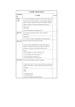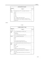
POT-
OFTM
Use it to adjust the length of time for the detection of a disconnected
connector or to adjust the potential sensor offset.
By default, the machine executes idle rotation of the fixing roller for 1
seconce every 30 min to prevent deformation of the roller while in
standby.
2
Settings range: 5 to 50 (unit: sec)
at time of shipment/upon RAM initialization: 5
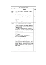
FXWRNL
VL
Use it to set the fixing upper roller alert level.
Use it to change the alert level in relation to the fixing counter reading.
If you have replaced the fixing roller or the fixing unit with a modified
type (with a longer life), use this mode to set the level to suit the new
type: i.e., change the setting of the following service mode item to '1' or
'2': COPIER>OPTION>BODY>FXRWNLVL. Then, decrease the
following setting slightly: COPIER>COUNTER>MISC>FX-UP-RL.
Make copies to see that the appropriate alert is issued when the counter
reaches a specific setting.
2
Settings range
0: 180,000
1: 150,000
2: 120,000
at time of shipment/upon RAM initialization: 0
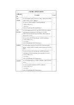
FXERRL
VL
Use it to change the fixing roller error level setting.
Use it to change the error level of the fixing counter count. If you have
replaced the fixing roller or the fixing unit with a modified type (with a
longer life), change the setting to suit the new type. The threshold of the
fixing error level will be in relation to the setting made using the
following service mode (offset by the level you set here):
COPIER>OPTION>BODY>FXWRNLVL.
2
Settings
0: +20,000
1: +40,000
2: +60,000
3: no error (alert retained)
at time of shipment/upon RAM initialization: 0
COPIER>OPTION>BODY
Subheadi
ng
Contents
Level
Summary of Contents for iR C6800 Series
Page 1: ...Jan 20 2005 Portable Manual iR C6800 Series ...
Page 2: ......
Page 6: ......
Page 12: ......
Page 13: ...Chapter 1 Maintenance and Inspection ...
Page 14: ......
Page 16: ......
Page 20: ...Chapter 1 1 4 Under high humidity and high temperature condition 85 000 images ...
Page 51: ...Chapter 2 Standards and Adjustments ...
Page 52: ......
Page 79: ...F 2 27 1 ...
Page 99: ...F 2 88 F 2 89 1 OK NG NG ...
Page 110: ......
Page 111: ...Chapter 3 Error Code ...
Page 112: ......
Page 114: ......
Page 172: ......
Page 173: ...Chapter 4 User Mode Items ...
Page 174: ......
Page 176: ......
Page 188: ...LIPS emulation 12 items utility printer initialize yes no Item Description ...
Page 190: ......
Page 191: ...Chapter 5 Service Mode ...
Page 192: ......
Page 380: ......
Page 381: ...Chapter 6 Outline of Components ...
Page 382: ......
Page 384: ......
Page 387: ...F 6 1 SL7 CL3 CL2 SL6 SL8 SL9 SL2 SL1 SL4 SL3 SL5 CL1 SL10 SL11 SL12 ...
Page 397: ...F 6 5 FM2 FM10 FM11 FM12 FM6 FM3 FM4 FM8 FM9 FM5 FM7 FM1 ...
Page 407: ...F 6 9 PS65 PS38 PS39 PS46 PS44 PS45 PS52 PS53 PS58 PS59 PS37 ...
Page 417: ...F 6 13 13 2 5 3 14 15 16 9 6 12 7 1 11 4 25 24 21 23 19 20 31 29 28 27 26 22 18 17 32 30 10 8 ...
Page 418: ......
Page 419: ...Chapter 7 System Construction ...
Page 420: ......
Page 422: ......
Page 443: ...Chapter 8 Upgrading ...
Page 444: ......
Page 446: ......
Page 455: ...Jan 20 2005 ...
Page 456: ......


