[2]
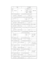
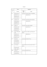
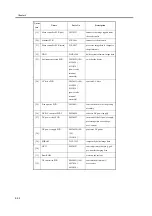
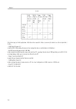
Potential control PCB
FM2-
0444(potential
sensor unit)
converts the potential sensor
output
[3]
Manual feed paper width
PCB
FH7-7600
detects the width of paper from the
manual feeder
[4]
Laser driver PCB
FM2-0394(laser
scanner)
controls the drive of the laser unit
[5]
Potential sensor
FM2-
0444(potential
sensor unit)
measures the surface potential of
the photosensitive drum
[6]
Drum heater PCB
FM2-0841(100/
120),
0842(230)
controls the drum heater
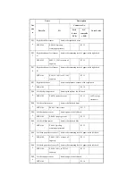
[7]
HVT2
FM2-0528
controls the developing (black,
color), primary transfer, primary
static eliminator bias
[8]
Keypad PCB
FM2-1250
controls the input information
from the keypad
[9]
Control panel inverter PCB
FM2-1251
controls the back-light activation
of the LCD
[10]
Control panel CPU PCB
FM2-1249
controls the panel
[11]
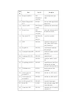
HVT3
FM2-0826
controls the secondary transfer
bias
[12]
Fixing/feeding driver PCB
FM2-0822
controls the sensors, motors, fans,
and solenoids of the fixing/
feeding and duplexing assemblies
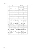
[13]
Environment sensor
FK2-0160
takes measurements of the
environment
[14]
Cassette 3 paper size
detection PCB
FM2-0849
detects the size of the cassette 3
[15]
Cassette 4 paper size
detection PCB
FM2-0849
detects the size of the cassette 4
[16]
DC/DC converter PCB 1
FM2-0832
converts DC power supply
[17]
SRAM PCB
FG3-2860
holds service mode settings/HDD
control information
[18]
Expansion bus PCB
FM2-0536
controls the color LCD controller,
card reader I/F
Notat
ion
Name
Parts No.
Description
Summary of Contents for iR C6800 Series
Page 1: ...Jan 20 2005 Portable Manual iR C6800 Series ...
Page 2: ......
Page 6: ......
Page 12: ......
Page 13: ...Chapter 1 Maintenance and Inspection ...
Page 14: ......
Page 16: ......
Page 20: ...Chapter 1 1 4 Under high humidity and high temperature condition 85 000 images ...
Page 51: ...Chapter 2 Standards and Adjustments ...
Page 52: ......
Page 79: ...F 2 27 1 ...
Page 99: ...F 2 88 F 2 89 1 OK NG NG ...
Page 110: ......
Page 111: ...Chapter 3 Error Code ...
Page 112: ......
Page 114: ......
Page 172: ......
Page 173: ...Chapter 4 User Mode Items ...
Page 174: ......
Page 176: ......
Page 188: ...LIPS emulation 12 items utility printer initialize yes no Item Description ...
Page 190: ......
Page 191: ...Chapter 5 Service Mode ...
Page 192: ......
Page 380: ......
Page 381: ...Chapter 6 Outline of Components ...
Page 382: ......
Page 384: ......
Page 387: ...F 6 1 SL7 CL3 CL2 SL6 SL8 SL9 SL2 SL1 SL4 SL3 SL5 CL1 SL10 SL11 SL12 ...
Page 397: ...F 6 5 FM2 FM10 FM11 FM12 FM6 FM3 FM4 FM8 FM9 FM5 FM7 FM1 ...
Page 407: ...F 6 9 PS65 PS38 PS39 PS46 PS44 PS45 PS52 PS53 PS58 PS59 PS37 ...
Page 417: ...F 6 13 13 2 5 3 14 15 16 9 6 12 7 1 11 4 25 24 21 23 19 20 31 29 28 27 26 22 18 17 32 30 10 8 ...
Page 418: ......
Page 419: ...Chapter 7 System Construction ...
Page 420: ......
Page 422: ......
Page 443: ...Chapter 8 Upgrading ...
Page 444: ......
Page 446: ......
Page 455: ...Jan 20 2005 ...
Page 456: ......

