Chapter 2
2-24
system software (R-CON).
2) Make the following selections in service mode, and
press the OK key to initialize the RAM:
C O P I E R > F U N C T I O N > C L E A R > R - C O N .
Thereafter, turn off and then on the main power.
3) Enter the settings for the following items in service
mode:
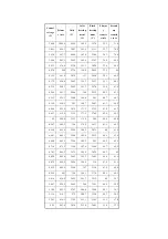
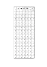
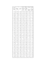
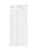
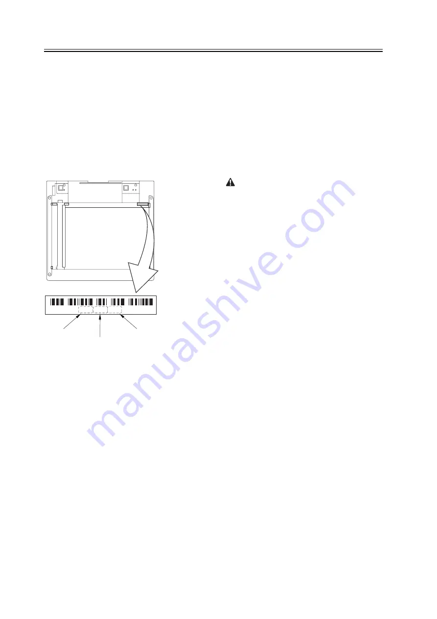
a. standard white plate white level data
COPIER>ADJUST>CCD>W-PLT-X,Y,Z
F-2-26
b. service label settings (label attached behind reader
unit front cover)
b-1 image read start position adjustment (x direction;
for fixed reading)
COPIER>ADJUST>ADJ-XY>ADJ-X
b-2 image read start position adjustment (Y direction;
fixed reading)
COPIER>ADJUST>ADJ-XY>ADJ-Y
b-3 shading position adjustment (for fixed reading)
COPIER>ADJUST>ADJ-XY>ADJ-S
b-4 feeder mode main scanning position adjustment
COPIER>ADJUST>ADJ-XY>ADJ-Y-DF
b-5 ADF stream reading CCD read position
adjustment
COPIER>ADJUST>ADJ-XY>STRD-POS
b-6 CCD unit-dependent RB/GB sub scanning
direction color displacement correction value
COPIER>ADJUST>CCD>CCDU-RG/GB
b-7 CCD unit-dependent RG/GB sub scanning
direction color displacement value at shipment
COPIER>ADJUST>CCD>FCCDU-RG/GB
b-8 auto gradation adjustment target value
COPIER>ADJUST>PASCAL>OFST-P-Y,M,C,K
2. ADF-Related Adjustments
The machine uses the RAM on its reader
controller to hold ADF-related service data; as such,
you must make the appropriate adjustments for the
ADF whenever you have replaced the reader
controller or initialized the RAM.
1) Enter the settings indicated on the P-PRINT
printout you have previously generated for the
following items:
a. original stop position adjustment
FEEDER>ADJSUT>DOCST
b. original feed speed (magnification) adjustment
FEEDER>ADUST>LA-SPEED
2) Make adjustments using the following items:
a. ADF sensor sensitivity adjustment
FEEDER>FUNCTION>SENS-INT
b. tray width adjustment
AB system:
FEEDER>FUNCTION>TRY-A4 and
FEEDER>FUNCTION>TRY-A5R
inch system:
FEEDER>FUNCTION>TRY-LTR
and FEEDER>FUNCTION>TRY-LTRR
c. white level adjustment
COPIER>FUNCTION>CCD>DF-WLVL1
COPIER>FUNCTION>CCD>DF-WLVL2
When done, put the P-PRINT printout [1] you have
previously generated in the service book, disposing of
the older printout, if any.
8 2 0 6 8 6 6 7 9 3 4 9
W - P L T - X
W - P L T - Y
W - P L T - Z
*
*
Summary of Contents for iR C6800 Series
Page 1: ...Jan 20 2005 Portable Manual iR C6800 Series ...
Page 2: ......
Page 6: ......
Page 12: ......
Page 13: ...Chapter 1 Maintenance and Inspection ...
Page 14: ......
Page 16: ......
Page 20: ...Chapter 1 1 4 Under high humidity and high temperature condition 85 000 images ...
Page 51: ...Chapter 2 Standards and Adjustments ...
Page 52: ......
Page 79: ...F 2 27 1 ...
Page 99: ...F 2 88 F 2 89 1 OK NG NG ...
Page 110: ......
Page 111: ...Chapter 3 Error Code ...
Page 112: ......
Page 114: ......
Page 172: ......
Page 173: ...Chapter 4 User Mode Items ...
Page 174: ......
Page 176: ......
Page 188: ...LIPS emulation 12 items utility printer initialize yes no Item Description ...
Page 190: ......
Page 191: ...Chapter 5 Service Mode ...
Page 192: ......
Page 380: ......
Page 381: ...Chapter 6 Outline of Components ...
Page 382: ......
Page 384: ......
Page 387: ...F 6 1 SL7 CL3 CL2 SL6 SL8 SL9 SL2 SL1 SL4 SL3 SL5 CL1 SL10 SL11 SL12 ...
Page 397: ...F 6 5 FM2 FM10 FM11 FM12 FM6 FM3 FM4 FM8 FM9 FM5 FM7 FM1 ...
Page 407: ...F 6 9 PS65 PS38 PS39 PS46 PS44 PS45 PS52 PS53 PS58 PS59 PS37 ...
Page 417: ...F 6 13 13 2 5 3 14 15 16 9 6 12 7 1 11 4 25 24 21 23 19 20 31 29 28 27 26 22 18 17 32 30 10 8 ...
Page 418: ......
Page 419: ...Chapter 7 System Construction ...
Page 420: ......
Page 422: ......
Page 443: ...Chapter 8 Upgrading ...
Page 444: ......
Page 446: ......
Page 455: ...Jan 20 2005 ...
Page 456: ......

