Chapter 2
2-23
2.3
Scanning System
2.3.1
After Replacing the
CCD Unit
0003-9936
iR C6800C / iR C6800CN / iR 5800C / iR 5800CN
If you have replaced the CCD unit, be sure to enter the
settings indicated on the label attached to the CCD
unit:
COPIER>ADJUST>CCD>CCDU-RG
(to enter the correction value for CCD-dependent RG
color displacement in sub scanning direction)
COPIER>ADJUST>CCD>CCDU-GB
(to enter the correction value for CCD-dependent GB
color displacement in sub scanning direction)
F-2-24
Moreover, be sure to update the settings indicated on
the service label attached behind the reader unit front
cover with the settings indicated on the label attached
to the CCD unit.
2.3.2
After Replacing the
Copyboard Glass
0003-8724
iR C6800C / iR C6800CN / iR 5800C / iR 5800CN
If you have replaced the copyboard glass, be sure to
enter the bar code value indicated in the upper
right of the copyboard glass using the following
service mode items:
COPIER>ADJUST>CCD>W-PLT-X
COPIER>ADJUST>CCD>W-PLT-Y
COPIER>ADJUST>CCD>W-PLT-Z
(to enter the standard white plate white level data X,
Y, Z)
F-2-25
2.3.3
After Replacing the
Reader Controller PCB or
Initializing the RAM
0003-8726
iR C6800C / iR C6800CN / iR 5800C / iR 5800CN
- Be sure to generate the latest P-PRINT printout
before replacing the reader controller PCB.
<if you are initializing the RAM of the reader
controller without replacing the PCB>
- Using the SST, upload the backup data of the reader
controller; then, after initializing the RAM, download
the data to eliminate the need for the following
adjustments:
1. Reader Unit-Related Adjustments
1) Using the SST, download the latest version of the
+2,-1,30524101
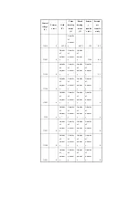
CCDU-RG
CCDU-GB
8 2 0 6 8 6 6 7 9 3 4 9
W - P L T - X
W - P L T - Y
W - P L T - Z
*
*
Summary of Contents for iR C6800 Series
Page 1: ...Jan 20 2005 Portable Manual iR C6800 Series ...
Page 2: ......
Page 6: ......
Page 12: ......
Page 13: ...Chapter 1 Maintenance and Inspection ...
Page 14: ......
Page 16: ......
Page 20: ...Chapter 1 1 4 Under high humidity and high temperature condition 85 000 images ...
Page 51: ...Chapter 2 Standards and Adjustments ...
Page 52: ......
Page 79: ...F 2 27 1 ...
Page 99: ...F 2 88 F 2 89 1 OK NG NG ...
Page 110: ......
Page 111: ...Chapter 3 Error Code ...
Page 112: ......
Page 114: ......
Page 172: ......
Page 173: ...Chapter 4 User Mode Items ...
Page 174: ......
Page 176: ......
Page 188: ...LIPS emulation 12 items utility printer initialize yes no Item Description ...
Page 190: ......
Page 191: ...Chapter 5 Service Mode ...
Page 192: ......
Page 380: ......
Page 381: ...Chapter 6 Outline of Components ...
Page 382: ......
Page 384: ......
Page 387: ...F 6 1 SL7 CL3 CL2 SL6 SL8 SL9 SL2 SL1 SL4 SL3 SL5 CL1 SL10 SL11 SL12 ...
Page 397: ...F 6 5 FM2 FM10 FM11 FM12 FM6 FM3 FM4 FM8 FM9 FM5 FM7 FM1 ...
Page 407: ...F 6 9 PS65 PS38 PS39 PS46 PS44 PS45 PS52 PS53 PS58 PS59 PS37 ...
Page 417: ...F 6 13 13 2 5 3 14 15 16 9 6 12 7 1 11 4 25 24 21 23 19 20 31 29 28 27 26 22 18 17 32 30 10 8 ...
Page 418: ......
Page 419: ...Chapter 7 System Construction ...
Page 420: ......
Page 422: ......
Page 443: ...Chapter 8 Upgrading ...
Page 444: ......
Page 446: ......
Page 455: ...Jan 20 2005 ...
Page 456: ......


