COPYRIGHT © 2001 CANON INC.
2000 2000 2000 2000
CANON CLC5000 REV.0 JAN. 2001
CHAPTER 3 INSTALLATION
3-15
Step
Work
Remarks
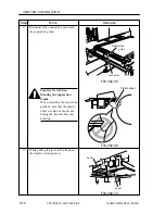
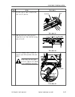
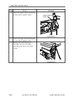
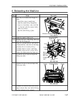
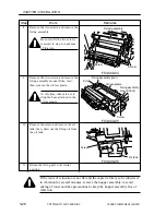
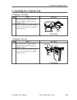
F03-303-03
F03-303-04
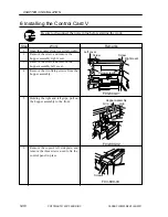
Right cover
Screw
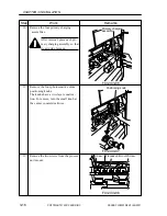
Fixing screws
Grip
Grip
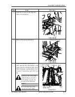
Lever
Transfer unit
F03-303-05
5
Perform the same steps for the M, Y, and
Bk toners as for the C toner.
Do not dispose of the toner
bottle in fire; it may tear open
or explode.
6
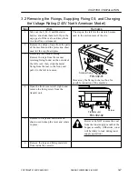
Open the right cover, and remove the
hopper assembly right cover (1 screw).
7
Remove the two fixing screws from the
hopper assembly.
8
Holding both left and right grips, pull the
hopper assembly to the front and then lift
it. (It will be locked when lifted to the
topmost position.)
Check to make sure that the
hopper assembly is securely
locked in position by the naked
eye.
9
• Shift down the lever of the transfer
unit, and release the transfer belt from
the photosensitive drum.
Summary of Contents for CLC 5000
Page 7: ...Main Body Accessory COPYRIGHT 2001 CANON INC 2000 2000 20000 CANON CLC5000 REV 0 JAN 2001 ...
Page 574: ...COPYRIGHT 2001 CANON INC 2000 2000 2000 2000 CANON CLC5000 REV 0 JAN 2001 APPENDIX ...
Page 578: ...COPYRIGHT 2001 CANON INC 2000 CANON CLC5000 REV 0 JAN 2001 A 4 Blank page ...
Page 587: ...Service Mode COPYRIGHT 2001 CANON INC 2000 CANON CLC5000 REV 0 JAN 2001 ...
Page 725: ...Error Code COPYRIGHT 2001CANONINC 2000CANONCLC5000REV 0JAN 2001 ...
Page 727: ...COPYRIGHT 2001 CANON INC 2000 CANON CLC5000 REV 0 JAN 2001 ii CONTENTS Blank page ...

