2-7
CHAPTER 2 NEW FUNCTIONS
COPYRIGHT © 2001 CANON INC.
2000 2000 2000 2000
CANON CLC5000 REV.0 JAN. 2001
2. Detecting the Activation of the Scanning Lamp
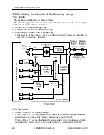
As long as the scanning lamp (LA1) remains on, the lamp ON detection circuit also re-
mains on to generate the ON detection signal to the timer circuit.
If the scanning lamp remains on for about 60 sec for some reason (e.g., fault), the timer
circuit turns on the error latching circuit to force the LAON signal to go ‘0’, thereby
turning off the lamp. At the same time, the lamp error single (LAERR) is sent to the
reader controller PCB; and, as a result, the machine will indicate ‘E220’ on its control
panel and shut itself off.
To reset the machine, remove the cause, and turn on the power switch.
The machine is equipped with the following two protective mechanisms to prevent mal-
function of the scanning lamp:
• If the temperature inside the thermal switch exceeds 175ºC , one of two thermal
switches will turn off to cut off the power to the scanning lamp.
• If overcurrent flows because of a short circuit or the like around the scanning lamp,
the fuse (FU1) turns off to cut off the power to the lamp regulator.
The thermal switches 1 and 2 (TP4, TP5) are used on the DC line, subject-
ing the contacts to damage when they turn on. Do not use them once they
have turned on to avoid unreliable operation after the machine has been re-
set.
3. Controlling the Intensity for the Scanning Lamp
The intensity of the scanning lamp is determined by the value of the intensity adjust-
ment signal (LACNTL) from the reader controller PCB.
The intensity control circuit inside the lamp regulator sends pulse signals (PWM) to the
switching circuit according to the level of the LACNTL signal; and the switching circuit
repeats turning on and off at short intervals in response; these intervals are varied to con-
trol the current flowing to the scanning lamp (hence its intensity).
The level LACNTL signal is determined when FUNC>CCD>AUTO-ADJ is executed in
service mode; once determined, it remains the same. It is important to execute
FUNC>CCD>AUTO-ADJ whenever you have replaced the reader controller PCB the
standard white plate, the reader controller PCB flash memory, CCD unit, the analog pro-
cessor PCB.
Summary of Contents for CLC 5000
Page 7: ...Main Body Accessory COPYRIGHT 2001 CANON INC 2000 2000 20000 CANON CLC5000 REV 0 JAN 2001 ...
Page 574: ...COPYRIGHT 2001 CANON INC 2000 2000 2000 2000 CANON CLC5000 REV 0 JAN 2001 APPENDIX ...
Page 578: ...COPYRIGHT 2001 CANON INC 2000 CANON CLC5000 REV 0 JAN 2001 A 4 Blank page ...
Page 587: ...Service Mode COPYRIGHT 2001 CANON INC 2000 CANON CLC5000 REV 0 JAN 2001 ...
Page 725: ...Error Code COPYRIGHT 2001CANONINC 2000CANONCLC5000REV 0JAN 2001 ...
Page 727: ...COPYRIGHT 2001 CANON INC 2000 CANON CLC5000 REV 0 JAN 2001 ii CONTENTS Blank page ...

