2-245
CHAPTER 2 NEW FUNCTIONS
COPYRIGHT © 2001 CANON INC.
2000 2000 2000 2000
CANON CLC5000 REV.0 JAN. 2001
9.7.4 Fans and Motors
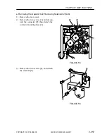
a. Removing the Buffer Pass Motor (M1, M3)
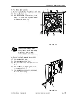
1) Remove the rear cover.
2) Disconnect the two connectors [1], and
remove the two screws [2]; then, detach
the buffer pass motor [3].
F02-907-32
Memo
The buffer pass input motor
(M1) and the buffer pass output
motor (M3) may be disas-
sembled in the same way.
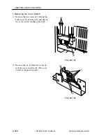
b. Removing the Reversal Motor (M2)
1) Remove the rear cover.
2) Remove the right front cover.
3) Disconnect the connector of the reversal
motor.
4) Remove the vertical path guide assem-
bly. (See F02-907-12.)
5) Remove the two screws [1], and detach
the reversal motor [2].
F02-907-33
[2]
[1]
[1]
[3]
[3]
[2]
[2]
Summary of Contents for CLC 5000
Page 7: ...Main Body Accessory COPYRIGHT 2001 CANON INC 2000 2000 20000 CANON CLC5000 REV 0 JAN 2001 ...
Page 574: ...COPYRIGHT 2001 CANON INC 2000 2000 2000 2000 CANON CLC5000 REV 0 JAN 2001 APPENDIX ...
Page 578: ...COPYRIGHT 2001 CANON INC 2000 CANON CLC5000 REV 0 JAN 2001 A 4 Blank page ...
Page 587: ...Service Mode COPYRIGHT 2001 CANON INC 2000 CANON CLC5000 REV 0 JAN 2001 ...
Page 725: ...Error Code COPYRIGHT 2001CANONINC 2000CANONCLC5000REV 0JAN 2001 ...
Page 727: ...COPYRIGHT 2001 CANON INC 2000 CANON CLC5000 REV 0 JAN 2001 ii CONTENTS Blank page ...

