COPYRIGHT © 2001 CANON INC.
2000 2000 2000 2000
CANON CLC5000 REV.0 JAN. 2001
xii
CONTENTS
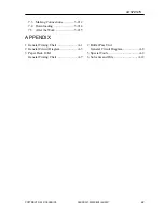
2.7.10 Adjusting the Pressure of the
Paper Deck Separation/Feeding
Roller ................................. 5-39
2.7.11 Positioning the Cassette Pickup
Roller Releasing Solenoid
(SL9, SL10) ....................... 5-39
2.7.12 Adjusting the Pressure of the
Multifeeder Separation
Roller ................................. 5-40
2.7.13 Adjusting the Position of the
Multifeeder Pick-Up Roller
Releasing Solenoid
(SL5) .................................. 5-40
2.7.14 Adjusting the Position of the
Delivery Paper Deflecting Plate
Solenoid (SL14) ................ 5-40
2.7.15 Adjusting the Position of the
Duplexing Unit Paper Deflect-
ing Plate Solenoid
(SL11) ................................ 5-41
2.7.16 Adjusting the Position of the
Duplexing Unit Stacking
Assembly Paper Guide
Plate ................................... 5-41
2.7.17 Adjusting the Position of the
Duplexing Unit Feeding Roller
Solenoid (SL13) ................ 5-42
2.7.18 Attaching the Timing Belt for
the Duplexing Unit Stacking
Assembly Paper Guide
Plate ................................... 5-42
2.7.19 Adjusting the Position of the
Separation Claw Solenoid
(SL15) ................................ 5-43
2.7.20 Adjusting the Position of the
Upper Fixing Web Take-Up
Solenoid (SL3) .................. 5-43
2.7.21 When Replacing the
Registration Roller Unit .... 5-43
2.7.22 Correcting Skew
Movement(slope of the
registration roller unit) ....... 5-44
2.8
Laser Exposure System ............ 5-45
2.8.1
When Replacing the Laser
Unit .................................... 5-45
2.8.2
When Replacing the Video Con-
troller PCB ......................... 5-45
2.8.3
When Replacing the BD
Unit .................................... 5-45
2.8.4
Adjusting the Laser Power 5-45
2.8.5
Adjusting the Laser
Intensity ............................. 5-49
2.8.6
Laser Focus Adjustment .... 5-50
2.9
Fixing Assembly-Related Parts 5-52
2.9.1
Points to Note When Replacing
the Fixing Heater ............... 5-52
2.9.2
Adjusting the Nip (fixing pres-
sure adjusting nut) ............. 5-52
2.9.3
Adjusting the Mounting Posi-
tion of the External Paper
Delivery Unit ..................... 5-53
2.10 Electrical .................................. 5-54
2.10.1 When Replacing Major
Parts ................................... 5-54
2.10.2 Checking the Environment
Measurement PCB ............. 5-58
2.10.3 Checking the High Voltage
Control System .................. 5-60
2.10.4 Checking the
Photointerrupters ............... 5-61
3 Troubleshooting Image Problems ..... 5-66
3.1
Initial Checks ........................... 5-66
3.1.1
Checking the Site of
Installation ......................... 5-66
3.1.2
Checking the Originals ...... 5-66
3.1.3
Checking the Copyboard Cover,
Copyboard Glass, and
Standard White Plate ......... 5-66
3.1.4
Checking the Charging
Assemblies ......................... 5-66
3.1.5
Checking the Developing
Assembly ........................... 5-66
3.1.6
Checking the Paper ............ 5-66
3.1.7
Checking the Periodically
Replaced Parts ................... 5-67
3.1.8
Others ................................ 5-67
3.2
Standard Image ........................ 5-67
3.2.1
Gray Scale .......................... 5-67
3.2.2
Color Patches ..................... 5-67
3.2.3
Photo .................................. 5-67
Summary of Contents for CLC 5000
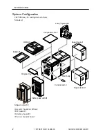
Page 7: ...Main Body Accessory COPYRIGHT 2001 CANON INC 2000 2000 20000 CANON CLC5000 REV 0 JAN 2001 ...
Page 574: ...COPYRIGHT 2001 CANON INC 2000 2000 2000 2000 CANON CLC5000 REV 0 JAN 2001 APPENDIX ...
Page 578: ...COPYRIGHT 2001 CANON INC 2000 CANON CLC5000 REV 0 JAN 2001 A 4 Blank page ...
Page 587: ...Service Mode COPYRIGHT 2001 CANON INC 2000 CANON CLC5000 REV 0 JAN 2001 ...
Page 725: ...Error Code COPYRIGHT 2001CANONINC 2000CANONCLC5000REV 0JAN 2001 ...
Page 727: ...COPYRIGHT 2001 CANON INC 2000 CANON CLC5000 REV 0 JAN 2001 ii CONTENTS Blank page ...

