CHAPTER 2 NEW FUNCTIONS
2-121
COPYRIGHT © 2001 CANON INC.
2000 2000 2000 2000
CANON CLC5000 REV.0 JAN. 2001
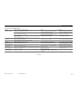
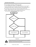
6.2 Outline of the Fixing System
T02-602-01
Unit/part
Fixing drive assembly
Fixing heater
Thermistor
Fixing roller temperature
control mechanism
Fixing oil temperature con-
trol mechanism
Protective mechanism
Oil applying assembly
Difference from CLC1000 Series machines
Control of fixing speed (from 6 to 4 steps)
Elimination of the gloss selection function
Increase of nip pressure
Different fixing speed: in the case of a transparency, 138 mm/sec until its leading edge
reaches the nip; thereafter, 68 mm/sec
Increase of power to the fixing heater
(upper: from 650 W to 800 W; lower: from 550 W to 600 W)
Addition of sub thermistor (upper, lower)
Change in the fixing roller control temperature
Addition of fixing oil temperature control
Addition of an oil heater, heater thermistor, oil temperature thermistor, thermal switch
Addition of protective functions
Addition of a scraper blade
Purpose
To review speed in support of high-speed operation
To eliminate the gloss selection function
To increase the latitude of fixing temperature control in
accommodating higher speed of operation
To support higher speed of operation
To support higher speed of operation
To increase the accuracy of error detection
To review temprature in support of higher operation
To stabilize the viscosity of oil, thereby stabilizing the
amount of application
Addition of a sub thermistor
Addition of a fixing oil heater
To scrape off offset toner, thereby stabilizing the amount of
oil application
Reference
6.3 “Outline of Fixing/Delivery Assembly”
6.8 “Timing Chart (fixing/delivery assembly)”
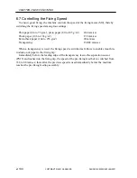
6.7 “Controlling the Fixing Speed”
6.7 “Controlling the Fixing Speed”
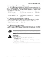
6.4 “Controlling the Fixing Roller Temperature”
6.4 “Controlling the Fixing Roller Temperature”
6.4 “Controlling the Fixing Roller Temperature”
6.8 “Timing Chart (fixing/delivery assembly”)
6.5 “Controlling the fixing oil temperature”
6.8 “Timing Chart (fixing/delivery assembly)”
6.6 “Protective Mechanism”
—
Summary of Contents for CLC 5000
Page 7: ...Main Body Accessory COPYRIGHT 2001 CANON INC 2000 2000 20000 CANON CLC5000 REV 0 JAN 2001 ...
Page 574: ...COPYRIGHT 2001 CANON INC 2000 2000 2000 2000 CANON CLC5000 REV 0 JAN 2001 APPENDIX ...
Page 578: ...COPYRIGHT 2001 CANON INC 2000 CANON CLC5000 REV 0 JAN 2001 A 4 Blank page ...
Page 587: ...Service Mode COPYRIGHT 2001 CANON INC 2000 CANON CLC5000 REV 0 JAN 2001 ...
Page 725: ...Error Code COPYRIGHT 2001CANONINC 2000CANONCLC5000REV 0JAN 2001 ...
Page 727: ...COPYRIGHT 2001 CANON INC 2000 CANON CLC5000 REV 0 JAN 2001 ii CONTENTS Blank page ...

