COPYRIGHT © 2001 CANON INC.
2000 2000 2000 2000
CANON CLC5000 REV.0 JAN. 2001
CHAPTER 3 INSTALLATION
3-41
Step
Work
Remarks
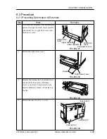
screw
Developing bias assembly
protection member
Hole
Hole
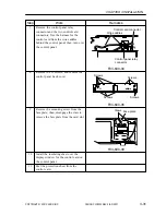
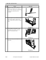
8.2.3 Mounting the Developing Bias Assembly Protection Member
1
Remove the M4x8 screw used to secure
the power cord base in place.
2
Secure the developing bias protection
member(left side in the illsutration) to the
power cord base using the M4x8mm
screw removed in step1 as shown. Using
the M4x8mm screw used to hold the rear
cover, secure the developing bias
assembly protection member to the rear of
the base plate.
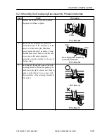
3
Lead the belt through the gap of the belt
retaining member. Before suspending the
machine, apply light tension, and check to
make sure that the belt is in contact with
the top surface of the retaining member at
four points.
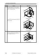
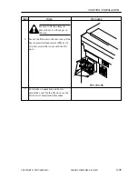
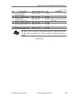
F03-802-08
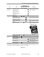
F03-802-09
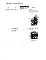
F03-802-11
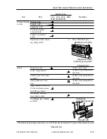
F03-802-10
Summary of Contents for CLC 5000
Page 7: ...Main Body Accessory COPYRIGHT 2001 CANON INC 2000 2000 20000 CANON CLC5000 REV 0 JAN 2001 ...
Page 574: ...COPYRIGHT 2001 CANON INC 2000 2000 2000 2000 CANON CLC5000 REV 0 JAN 2001 APPENDIX ...
Page 578: ...COPYRIGHT 2001 CANON INC 2000 CANON CLC5000 REV 0 JAN 2001 A 4 Blank page ...
Page 587: ...Service Mode COPYRIGHT 2001 CANON INC 2000 CANON CLC5000 REV 0 JAN 2001 ...
Page 725: ...Error Code COPYRIGHT 2001CANONINC 2000CANONCLC5000REV 0JAN 2001 ...
Page 727: ...COPYRIGHT 2001 CANON INC 2000 CANON CLC5000 REV 0 JAN 2001 ii CONTENTS Blank page ...

