2-123
CHAPTER 2 NEW FUNCTIONS
COPYRIGHT © 2001 CANON INC.
2000 2000 2000 2000
CANON CLC5000 REV.0 JAN. 2001
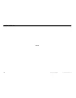
M9
SL3
SL4
M30
Fixing
web take-up
solenoid
One-way
clutch
Fixing
upper web
Fixing
web motor
Oil applying
roller
Fixing motor
Web length
sensor (PS36)
Oil level
sensor (PS6)
Fixing upper
web releasing
solenoid
Upper oil pan
Lower oil pan
Fixing upper roller
Fixing lower web
Fixing lower roller
Oil removing blade
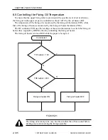
6.3 Outline of the Fixing/Delivery Assembly
The following are driven by the fixing motor (M9):
• Fixing upper roller
• Lower fixing roller
• Delivery roller
• Oil applying roller
• Fixing upper web lock
To ensure good fixing invariably in duplex, transparency, or normal mode, the machine
changes its fixing speed among four levels.
The upper roller and the lower roller are each provided with a fixing cleaning web. The
fixing upper web is driven by the fixing upper web take-up solenoid (SL3), and the lower
web is driven by the fixing web motor (M30).
The fixing lower roller is also provided with a cleaning blade of a spring type.
The separation claws used to prevent paper from wrapping around the fixing lower roller
are made to move away from the fixing lower roller by the drive of the separation claw sole-
noid (SL15) to prevent scratches on the roller.
F02-603-01
Summary of Contents for CLC 5000
Page 7: ...Main Body Accessory COPYRIGHT 2001 CANON INC 2000 2000 20000 CANON CLC5000 REV 0 JAN 2001 ...
Page 574: ...COPYRIGHT 2001 CANON INC 2000 2000 2000 2000 CANON CLC5000 REV 0 JAN 2001 APPENDIX ...
Page 578: ...COPYRIGHT 2001 CANON INC 2000 CANON CLC5000 REV 0 JAN 2001 A 4 Blank page ...
Page 587: ...Service Mode COPYRIGHT 2001 CANON INC 2000 CANON CLC5000 REV 0 JAN 2001 ...
Page 725: ...Error Code COPYRIGHT 2001CANONINC 2000CANONCLC5000REV 0JAN 2001 ...
Page 727: ...COPYRIGHT 2001 CANON INC 2000 CANON CLC5000 REV 0 JAN 2001 ii CONTENTS Blank page ...

